background image


P a g e


36 

Réf. : 450100 FR


5.1.5 – Drive belt tension 

(must be carried out with the engine stopped)

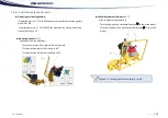
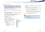
Belt tension  is  given  by the variation  in  pitch  diameter of  pulleys  by 
means of wedge sets. The drive pulley and the driven pulley are both 
adjustable.  To  access  the  pulleys,  disassemble  the  wheel,  the  wheel 
casing and the belt casing.  

Every 50 operating hours, check belt tension and adjust if necessary as 
follows: 

-


Disassemble the flange from the pulley Item 

 held by nuts Item 

-


Remove a wedge Item 

-


Reassemble the flange Item 

 placing the wedge Item 

② 

between 

the flange and the nuts Item 

③.


-


Progressively tighten the six nuts Item 

, while rotating the pulley 

manually so  that  the  belt assumes  its  position  without  being  stuck 
between the two flanges. 


If the resulting tension is not sufficient, repeat the operation

.


To guarantee proper belt alignment, the same adjustment must be performed 
on each pulley. 

When there are no more wedges between the flanges of the two pulleys and 
the belt spins, the belt must be replaced with a new belt. 

To assemble a new belt, fit all the wedges (2 per pulley) between the pulley 
flanges. 


Run a first belt tension check after 10 hours’ use of the machine, then check 
and adjust tension if necessary every 50 hours. 


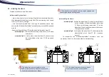
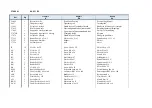
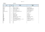
NEW BELT 

WORN BELT 

1


2


3


2


1


   When replacing or putting back a belt, check that the pulley 
grooves are in proper condition and clean them as well as the 
belt grooves thoroughly.


Содержание MP.12

Страница 1: ...MEULEUSE DE PROFILS MP 12 RAIL PROFILE GRINDING MACHINE ANGLAIS French Original handbook Ref 450100 Gb ...

Страница 2: ...En cohérence avec notre politique de respect de l environnement cette notice a été réalisée sur un papier éco responsable ...

Страница 3: ...f the world of railways This machine built entirely in France from design through to delivery has been subjected to continuous extremely strict controls Formed of different mechanical elements assembled by highly qualified fitters your machine has been tested calibrated and controlled at every stage of its production We are convinced that it will give you every satisfaction and are of course at yo...

Страница 4: ... 3 1 Inspecting the machine 26 3 2 Installing the wheel 27 3 3 Adjusting the guide rollers 28 3 3 1 Adjustment for Vignole rails 28 3 3 2 Adjustment for grooved rails if equipped with grooves 28 3 4 Fuel 29 3 4 1 General instructions 29 3 4 2 Refuelling 29 CHAPTER 4 Using the machine 30 4 1 Starting and stopping 30 4 2 Operating the machine 31 4 2 1 Use on Vignole rail 31 4 2 2 Use on a grooved ra...

Страница 5: ...ovided by the Machines Directive 2006 42 EC Its aim is to guarantee easy correct understanding of its use for operators responsible for operating and performing maintenance on the battery operated machine Should anything not be clear in the handbook we ask operators to immediately request explanations from the manufacturer so as to avoid misinterpretations that could jeopardise safety This instruc...

Страница 6: ...o identify a procedure or throw light on a matter BOLD TEXT highlights the notion Pictograms Combustion engine explanations Read this instruction handbook thoroughly and fully before first use Keep it in a safe place so you can read it again for future use Visual protective equipment must be worn Hearing protective equipment must be worn as per applicable site regulations Engine speed regulation S...

Страница 7: ...Ref 450100 FR P a g e 5 Pictograms Combustion engine explanations Minimum number of carriers Location of unobvious carrying handles Wheel rotation direction To stop the Honda engine On the lifting zones ...

Страница 8: ...rictly comply with the site general safety instructions laid down by the site supervisor particularly if work is conducted without interruption of traffic Use servicing and repair of equipment must be carried out by competent personnel having received thorough training beforehand While the technical documentation and instructions will usefully complete knowledge acquired during training sessions o...

Страница 9: ...necessary physical and mental conditions to allow risk free work The work zone must be free of obstacles The work zone and its surroundings must be clear of flammable materials If something is not clear whether concerning the machine or the work to be performed ask a qualified person Do not make assumptions This equipment must not be used in explosive atmospheres Avoid working positions where exha...

Страница 10: ...nstallations of the machine can only be carried out by accredited persons It is necessary to read and understand all the signs placed on the machine and to comply with their instructions The signs present on the machine contain pictograms nameplates and instruction labels They must be cleaned or replaced if they are damaged missing or illegible If one of these items is found on a replaced part a n...

Страница 11: ...ely fill tanks with fuel when the machines have been heated Never exceed three quarters of tank capacity When refuelling machines that have been heated if fuel starts to bubble in the tank screw back on the filler cap immediately and let the machine cool down Only use fuel appropriate for the engine with which the machine is equipped Consult the engine handbook Never breathe in fuel fumes If you n...

Страница 12: ...ur hand or release it suddenly After starting if machine operation is not satisfactory stop the engine and alert the maintenance manager For petrol engines only use spark plugs the end of which conforms to sketch 1 opposite If a nut is used ensure it is properly locked in place After reassembling the spark plug check that its cap is in good condition and secured properly onto the spark plug Genera...

Страница 13: ... insert a shield that will intercept the jet before it reaches any dangerous points bush fire hazard in summer Ensure the wheel is not struck during its operation as this could result in it bursting Ensure that the wheel is never in contact with a sleeper or ballast or with any other foreign object Before starting the machine check proper condition and fastening of the wheel protective cap Never m...

Страница 14: ...wheel to vertical position stop grinding and stop the engine before opening the fuel filler cap Never fill the fuel tank with more than of its capacity to avoid seepage when working with slanting engine Never work on a fuel tank or handle fuel for filling or any other reasons in zones where there may be Ignition sources e g blow torch sparks etc Incandescent materials or materials at high temperat...

Страница 15: ... without its protective casings and filter If compressed air is used for cleaning wear protective clothes a mask goggles and hearing protection If work takes place on a two way track pay particular attention to the traffic running on the track remaining free for circulation In all cases the machine must be used in accordance with the railway instructions applicable on its place of operation Use of...

Страница 16: ...ing handle Yellow background Riveted to the machine frame For SNCF approved machine Riveted to the machine frame Except SNCF 12937 Stuck to the engine air filter Blue background 37654 Stuck to the storage box on the operator side White background 12569 Stuck on each of the machine carrying arms Blue background 12670 Riveted to the machine chassis above the wheel casing REF Visual Position 12623 St...

Страница 17: ...p a similar product having reached its end of life or manufacturing residues Recycling has two major ecological consequences Reduction in waste volume and thus in the pollution that this waste would cause some materials take decades and even centuries to decompose Preservation of natural resources as the recycled material is used in the stead of the material that should have been extracted The GEI...

Страница 18: ...rdiness due to its non deformable alloy rigid chassis ensure operators an optimum comfort of use Its guide rollers and wide wheelbase guarantee continuity of grinding from the horizontal to the vertical position It has been entirely designed using the cutting edge techniques employed in the machine tool industry Manufacturer GEISMAR ALPES Route d Italie 38110 LA TOUR DU PIN Equipment description R...

Страница 19: ...heel adjustment flywheel C Engine stop D Engine E Handle F Guide roller G Wheel casing H Limit stop J Operating arm locking handle K Wheel lowering locking handle Photographs and illustrations for information only and non binding they may include options A B C D E E F F G H J K ...

Страница 20: ...es g kWh HC NOx 6 7 CO 365 Fuel Unleaded petrol Starting Launching the automatic recoil rope Machine Engine adjustment speed max speed rpm 3000 Wheel rotation speed rpm 3000 Wheel max diameter mm 150 Maximum cant for which the machine is stable mm N A Wheel Outer diameter mm 150 Inner diameter mm 55 Height mm 72 Wheel authorised rotation speed rpm 6370 Wheel authorised peripheral speed m sec 50 Wh...

Страница 21: ...pelvis and head respecting the natural curvature of the spine Force with your legs to prevent placing all the strain on your back You thus need to bend your legs and avoid bending your back Swivel on your feet to avoid twisting your trunk Stand so your feet are apart at shoulder width and place your feet flat on the ground to help you keep your balance Load distribution when lifting using the carr...

Страница 22: ...of which exceeds the machine weight defined in Chapter 2 3 Technical characteristics Pass inside the lifting points approved slings or straps appropriate for the weight to be lifted See Fig 1 Lift the machine gently and smoothly A safety perimeter defined by the site foreman must be complied with to prevent incorrect operations while the machine is being lifted This perimeter could be modified by ...

Страница 23: ...l profile grinding machine in a vehicle when the wheel is assembled 2 4 4 Installing the machine on the rail With the help of 4 operators grip the machine by the 4 carrying zones Item see chapter 2 4 1 Load distribution In a coordinated movement and on the orders of one of the operators lift the machine in order to move it and place it on the rail to be ground See chapter 2 7 Operator position The...

Страница 24: ...ating arm holder The aim of the holder is to keep the engine in the horizontal position throughout storage Check engine hoses after prolonged storage Storage protection Choice of storage protection systems depends on 2 main factors storage duration storage conditions unsheltered storage exposure to the elements and sheltered storage building closed or open shed awning etc Equipment must only be st...

Страница 25: ... Operating handle Item This handle lets the operator Move the machine from right to left on the weld Tilt the machine against himself up to 90 Tilt the machine in front of himself up to 15 Wheel adjustment flywheel Item Used to adjust wheel lowering Turn the flywheel in a clockwise direction to lower the wheel Turn the flywheel in an anticlockwise direction to raise the wheel INNER OUTER INNER OUT...

Страница 26: ...P a g e 24 Réf 450100 FR 2 5 Machine position in the gauge The diagram below shows the machine dimensions with respect to gauge UIC 505 1 nominal track gauge of 1435 320 440 760 ...

Страница 27: ...rk the operator must always be in the position shown in the photo below with his hands firmly holding the operating handle To adjust wheel height he must hold the operating handle in one hand and with the other operate the wheel adjustment flywheel This work position guarantees perfect machine control Position de l opérateur Operator position WORK ZONE If work calls for the operator to be outside ...

Страница 28: ...g and handling fuel before doing anything Engine oil level check the engine oil level using the dipstick and top up if required The level must be slightly lower than the maximum mark on the dipstick but must never exceed it Checking the safety equipment Start the engine be sure to refer to 4 1 Stopping and starting and check proper operation of the safety equipment engine remote stopping Checking ...

Страница 29: ...der plate Item 23 open end wrench Assembling the wheel assembly Fig 2 Position the wheel Item so that its inner Ø bears on the shoulder of the wheel holder plate Item Place the fastening screws Item on the wheel Item and bring them up until they touch Then tighten their screws assembly Fig 3 Lock in place the wheel Item then screw on the wheel holder plate Item 23 open end wrench To reassemble the...

Страница 30: ... tighten the nuts and counter nuts Item Repeat this assembly on the second guide roller 3 3 2 Adjustment for grooved rails if equipped with grooves Adjust one of the two guide rollers of the machine as follows Release the nuts Item and Item Place the machine on the rail positioning the guide rollers Item and Item in the groove Position the wheel Item aligning the outer edges of the rail and the wh...

Страница 31: ... ventilated place away from possible ignition sources such as blow torches sparks welding deposits To start the machine place it more than 6m from the filling point Closing the fuel filler cap Present the tank fuel filler cap opposite the filling orifice Screw on the cap Petrol GASOHOL and ALCOHOL are FORBIDDEN Engine oil Use a 4 stroke engine oil equivalent to or higher than engine requirements P...

Страница 32: ... engine idle for a few moments until speed stabilises and engine temperature rises When the engine starts to heat gradually bring the starter pull cord to the opening position Once the engine is hot increase speed up to the maximum limit stop Item factory setting Stopping the machine Stop the engine by closing the fuel valve Item STOP position The machine must only be started once it is on the tra...

Страница 33: ... this release the handle Item and bring up the two parts until they touch the limit stops Item Two intermediate positions are indicated by a ball type clip on mechanism These positions must be chosen to grind the rail curve However it is also possible to work in any other position To finish return to the rail top grinding position Then adjust the wheel precisely with respect to the rail profile To...

Страница 34: ...to the machine To this end loosen the handle Item separate the two parts arm machine as far as possible and retighten the handle Item To finish return to the rail top grinding position Then adjust the wheel precisely with respect to the rail profile To do this skim the wheel along the rail some sparks will appear You do not need to perform this operation in zones close to the weld but rather in zo...

Страница 35: ...ome to a complete standstill Free the machine from the track by proceeding in reverse order from placing the machine on the track described in 2 4 4 carrying points Item EMERGENCY procedure Stop the engine by setting the fuel valve to the STOP position item Grasp the machine by the operating handle and move the entire assembly off the track Emergency placing off the track of the machine shall take...

Страница 36: ...ools Supplied with the machine Servicing and maintenance tools not supplied with the machine MP12 2 stroke engine 13x23 open end wrench Pin wrench 10 bent tube wrench 17 open end wrench 4 H8x15 screws 4 W8 washers 2 stroke oil 100 mL Measuring cup 100 mL Spark plug wrench MP12 4 stroke engine 13x23 open end wrench Pin wrench 10 bent tube wrench 17 open end wrench 4 H8x15 screws 4 W8 washers Spark ...

Страница 37: ...r strictly to the manufacturer s instructions Regularly check engine idling maximum rotation speed using an electronic counter A check must be run before putting into service for the first time as atmospheric conditions and altitude may markedly modify this adjustment When checking or adjusting the machine must be installed on the work position on an assembly locked in place in order to measure en...

Страница 38: ...the six nuts Item while rotating the pulley manually so that the belt assumes its position without being stuck between the two flanges If the resulting tension is not sufficient repeat the operation To guarantee proper belt alignment the same adjustment must be performed on each pulley When there are no more wedges between the flanges of the two pulleys and the belt spins the belt must be replaced...

Страница 39: ...erage temperature for the place of use is within the indicated range 5 1 6 2 Checking and adjusting oil level Check oil level daily and adjust if necessary Cold engine Install the machine on a flat horizontal surface Release the handle Item and completely fold the operating arm Item holding back the machine to prevent it from suddenly toppling Gently topple the machine into its operating arm and w...

Страница 40: ... filler cap gauge Item Ⓒ and the washer Item Ⓑ Leave to flow out to the last drop to fully drain the worn oil Replace the oil drain plug with a new washer and fully tighten it With the engine in horizontal position fill the tank with fresh oil up to the maximum limit mark overflow point See 5 1 6 2 Checking and adjusting oil level To avoid oil from spilling onto the ground during level checking ti...

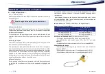
Страница 41: ...edule 5 1 7 2 Petrol filter Disassembling Place the fuel valve Item to the left in the CLOSED position 0 Unscrew the fuel decantation cup Remove the fuel filter sieve and the O ring seal Wash the decantation cup in a fireproof solvent and dry it completely Reassembling Place the O ring seal in the decantation cup Tighten the decantation cup to its maximum Place the fuel valve on the ON position I ...

Страница 42: ...g the side electrode Electrode spacing must be between 0 7 and 0 8 mm Put back the spark plug manually taking care not to damage its threading Once the spark plug has touched its centre continue to tighten it using a spark plug wrench to compress the sealing washer If the spark plug is new tighten it by 1 2 turn after it has touched its centre in order to compress the washer If it has already been...

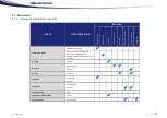
Страница 43: ...or 300h In case of damage As required Complete machine Inspect the machine Carry out overall cleaning with a clean cloth or a blow gun to eliminate any dirt deposited on the machine Greasing Grease Drive belt Adjust tension Replace Air filter Replace Engine oil Check level Replace Spark plug Check Adjust Replace Decantation cup Clean Idle engine rotation speed Check Valve clearance Check adjust ...

Страница 44: ...use After each use Each week After the first 10h First month or 20h Every 50h Every 6 months or 100h Every year or 300h Every 1000h In case of damage As required Combustion chamber Clean Fuel tank and filter Clean Fuel pipe Check Replace Pictogram Inspect the machine Replace The machine must be overhauled regularly This advice is not limited Continuous monitoring of the machine and carefully organ...

Страница 45: ...parts particularly when there is a safety risk Description Nb Replacement conditions Ø 35 x 45 x 7 10 wiper seal 1 Grease leak or incorrect operation No 25 O ring seal 1 AS 28 x 40 x 7 10 wiper seal 1 35 x 47 x 6 seal 1 V belt 1 Wear or breakage 40 mm bakelite ball 1 Ø 18 x 34 x 36 x 32 Flexibloc 2 Air filter 1 Periodic maintenance or incorrect operation Fuel filter 1 Spark plug 1 Hoses Periodic m...

Страница 46: ...ly should an incident of any kind occur Precautions of use During grinding take all necessary precautions to avoid directing the spark jet towards the second operator he must be equipped with goggles and gloves Do not bend the hose excessively as this could damage the drive and in some cases lead to accidents in the case of sudden breakage due to improper use After stopping the engine the hose sha...

Страница 47: ... grinding It is essential that the machine be equipped with an Ø 80mm wheel and a casing of the same diameter to perform proper rail grinding Wheel casing ref 37101 6 Ø 80 x 72 M20 type cup wheel ref N03313 Roller device for Vignole rail grooved rail passage ref 37000 BB 6 1 5 Anti vibration operating arm Anti vibration operating arm ref 37000 GF 6 1 6 Emergency stop button Emergency stop button a...

Страница 48: ...00738 M20 wheel holder plate or end 125 x 65 mm code N02780 80 x 72 mm code N03313 5 8 wheel holder end 150 x 65 mm code N00737 80 x 72 mm code N00731 6 x 3 code N03243 Wheel holder ends and plates accessories 5 8 wheel holder end ref 16356 M20 wheel holder end ref 16356 A Ø125 M20 wheel holder plate ref 16356 C 4 hole wheel holder plate M8 screws ref 37042 6 hole wheel holder plate M8 screws ref ...

Страница 49: ...Tableau d équivalence codes machine plans Table of equivalence machine codes plans MP 12_GX 270 ST471A07 MP 12_GX 270 ST471A55 MP 12_GX 270 ST471A57 37000 KJ 37000 PW 37000 PE 37000 PF 37000 NJ 37000 QD 37000 QE 37000 AQ LZ 37000 DS 37000 NN 12000 MS 12000 MR ...

Страница 50: ...K K ...

Страница 51: ...Axle Aksel B 10 Vis Chc 8 x 20 Screw Chc 8 x 20 Skrue Chc 8 x 20 AN 8 Vis H 8 x 35 Screw H 8 x 35 Skrue H 8 x 35 AP 2 Vis H 8 x 20 Screw H 8 x 20 Skrue H 8 x 20 AZ 1 Ecrou H 10 Nut H 10 Møtrik H 10 BC 1 Bille acier Ø 8 7 Steel ball Ø 8 7 Stålkugle Ø 8 7 FG 4 Rondelle M 8 U Washer M 8 U Spændskive M 8 U HA 1 Rondelle M 10 U Washer M 10 U Spændskive M 10 U KH 2 Rondelle W 8 Washer W 8 Spændskive W 8...

Страница 52: ...37000 PW 04 19 37120 R 1 1 x2 HONDAiGx 2701 Loctite 243 EUV FG 16078A 37702 G QS BKY BMR x2 Loctite 243 Q KH GP t 1 37027 ffi ...

Страница 53: ...péciale MP 1L Composition huile plan n 400126 Spécial oil MP G 1 Circlips 40e Circlips 40e Q 6 Ecrou H8 Nut H8 FG 4 Rondelle M 8 U Washer M 8 U GP 6 Goujon M8x32 Pin M8x32 KH 6 Rondelle W8 Washer W8 QS 1 Roulement à billes N 6008 EE Ball bearing N 6008 EE SB 12 Ecrou Nylstop M6 Safety nut M6 BMR 1 Clavette BD 6 35x6 35x30 T Wedge BD 6 35x6 35x30 T BKY 1 Courroie trapézoîdale SPA 13 x 11 x 800 V be...

Страница 54: ......

Страница 55: ... 6 x 15 BR 2 Vis Chc 10 x 30 Screw Chc 10 x 30 EA 3 Circlips 45 e Circlips 45 e EI 3 Rondelle W 10 Washer W 10 HA 1 Rondelle M 10 U Washer M 10 U JX 4 Vis Chc 6 x 15 Screw Chc 6 x 15 OP 1 Butée à billes n 51104 Thrust ball bearing n 51104 OQ 1 Roulement à billes n 6009 EE Ball bearing n 6009 EE SB 6 Ecrou nylstop de 6 Nylstop nut of 6 ABX 1 Roulement à billes n 6003 EE Ball bearing n 6003 EE ABZ 3...

Страница 56: ......

Страница 57: ...493 1 Levier Lever E 5 Vis H 6 x 15 Screw H 6 x 15 L 1 Vis H 10 x 20 Screw H 10 x 20 AR 6 Vis TF 90 6 x 15 Screw TF 90 6 x 15 BR 2 Vis Chc 10 x 30 Screw Chc 10 x 30 EA 3 Circlips 45 e Circlips 45 e EI 3 Rondelle W 10 Washer W 10 GQ 4 Vis H 6 x 10 Screw H 6 x 10 HA 1 Rondelle M 10 U Washer M 10 U JX 4 Vis Chc 6 x 15 Screw Chc 6 x 15 OP 1 Butée à billes n 51104 Thrust ball bearing n 51104 PK 2 Ecrou...

Страница 58: ... x Ø9 Ø 53 5 8 With 5 8 With 125 20 M 5 8 With 55 M22 x 150 90 4 x Ø9 Ø 53 5 8 With M22x150 53 20 M 5 8 With 54015 54059 37042 D 37042 37006 71028 71117 16356 16356 A 16356 C MP6 MP12 MOD 12 MP5 MV3 MP23 20 M 22 M x 150 71186 20 M 22 M X 150 71186 A 53 Ø 140 Ø M22x1 5 5 8 11 UNC 53 Ø 54015 B 28823 5 8 With 5 8 Whit 5 8 Whit 20 M 28507 ...

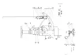
Страница 59: ...37000 QD R 05 19 DE DAV 1019 LYX DAV GQ 37707 37712 QRM QRC QRM QRF DAV DE YW JXA EWM HKU DE DAV EP Feuille 1 4 ...

Страница 60: ...37000 QD R 05 19 QRH 37699 QRH PX NCN DBU CSS NCN DBU 37706 37701 KIH FG AF GRY FM FG LBG 400119 Feuille 2 4 ...

Страница 61: ...37000 QD R 05 19 15 DBU ECB 37000 PZ PPL MZH RY DM 37690 13599 DM 37726 PX DAU NCN DBU 37726 entre DAU et NCN 37726 between DAU and NCN Feuille 3 4 ...

Страница 62: ...37000 QD R 05 19 QRS CJW 37699 37705 37687 AFK JH SM LBG 37715 37704 HNS CJW KKY 37718 37719 400115 LBG Loctite 243 Feuille 4 4 AFK GP ...

Страница 63: ... Washer M8 U FM 3 Vis H8 x 30 Screws H8 x 30 GP 1 Goujon 8 x 32 Stud 8 x 32 GQ 2 Vis H6 x 10 Screws H6 x 10 JH 1 Goujon 8 x 40 Stud 8 x 40 PX 2 Vis H5 x 15 Screws H5 x 15 RY 2 Rondelle M5 U Washer M5 U SM 1 Ecrou Hm 8 Nut Hm 8 YW 2 Plot diabolo type D Plot diabolo type D AFK 2 Ecrou frein H8 Brake nut H8 CJW 2 Passe fil Ø3 Bushing Ø3 CSS 1 Vis H5 x 25 Screws H5 x 25 DAU 1 Rondelle DI 5 Washer DI 5...

Страница 64: ...37000 QE R 05 19 PTH NEQ NEA noir black rouge red jaune yellow noir black M Feuille 1 2 ...

Страница 65: ......

Страница 66: ...37717 JZH 37000 QE R 05 19 Feuille 2 2 ...

Страница 67: ...is Anglais Fr Gb 37717 1 Faisceau arrêt moteur Engine stop beam JZH 1 Bouton poussoir Pushbutton NEA 1 Bouchon d étanchéité Sealing plug NEQ 1 x 0 09 m Gaine annelée fendue Ø16 Ringed split sheath Ø16 PTH 1 Clip Clip Ref Qty ...

Страница 68: ......

Страница 69: ...guidage Ø 120 mm BAE 4 Roulement à billes n 6005 ZZ 37 019 1 Lèvre de guidage Ø 170 mm 37 020 1 Axe de lèvre de guidage 1RAIL PROFILE GRINDING MACHINE Model MP 12 37 000 LZ 2 Runner Assy each including Ref Qty Description Ref Qty Description 5 110 1 Washer DIA 10 5 x 30 x 5 PS 2 Circlips 47 i 37 021 1 Runner axle TQ 2 Nylstop nut of 10 37 022 1 Runner plug APX 1 Ball bearing n 6204 ZZ 37 024 A 1 R...

Страница 70: ......

Страница 71: ...ille de raccordement de la gaine Connecting sheath 37125 1 Entraîneur de flexible Driving part of flexible shaft 37128 1 Bouchon baïonnette Bayonet plug EA 1 Circlips 45 e Circlips 45 e VZ 4 Vis H 6 x 12 Screw H 6 x 12 BXP 0 25 Chaînette Chain DAL 2 S de chainette S of chainette Ref Qty ...

Страница 72: ......

Страница 73: ...sing Ø150 Y 2 Vis H10 x 25 Screw H10x25 EI 2 Rondelle W10 Washer W10 Machine ST471H50 Machine ST471H50 37026 E 1 Carter pour meule Ø150 Øint 168 Grindstone casing Ø150 in Ø168 Y 2 Vis H10 x 25 Screw H10x25 EI 2 Rondelle W10 Washer W10 37026 F 1 Carter pour meule Ø150 fente de démontage de meule Grindstone casing Ø150 wheel disassembly Y 2 Vis H10 x 25 Screw H10x25 EI 2 Rondelle W10 Washer W10 3710...

Страница 74: ...12000 MS 10 18 R0 37685 1 13 23 37686 1 17 GBF 1 32 FCC 1 10 GBN 1 8 37088 1 GBS 1 AS 4 M8 x 15 KH 4 W8 Ref Qty A Pict ...

Страница 75: ...12000 MR 10 18 R1 37685 1 13 23 37686 1 17 FCC 1 10 37088 1 GBS 1 AF 4 M8 x 16 KH 4 W8 FJP 1 19 21 Ref Qty A Pict ...

Страница 76: ......

Страница 77: ......

Страница 78: ......

Отзывы: