gefran RK-5 C Скачать руководство пользователя страница 4

4

85201A_RK5C_User Manual_02-2017_ENG


2.2   OPERATING PARAMETERS SETTING

  After configuring the node parameters, the sensor can be integrated in the CANopen network. When powering on, the 

sensor transmits the boot-up message, and it goes into the Pre-operational state.

  Before requesting process data, configuration of operating parameters of the sensor can be performed. Configuration 

of operating parameters is made through SDO Services (Service Data Objects). Through SDO services, it is possible for 

example to change the transmission type of the PDO (Process Data Object) selecting the synchronous (through SYNC 

messages) or asynchronous (through event-timer) mode, or transmission time (event timer) of the asynchronous PDO.

  It is possible to save changed parameters in non-volatile memory accessing the Store Parameters object through SDO, 

or restore default parameters with the Restore Default Parameters object.

  It is possible to access all the objects specified in the Object Dictionary of the device (see Object Dictionary section).

  SDO Services are available in Pre-operational and Operational states only (see NMT Services section).


2.3   REQUESTING PROCESS DATA

  The GEFRAN RK5C CANopen position sensor provides one Transmit PDO (TPDO1), that includes position and speed 

data measured by the sensor.
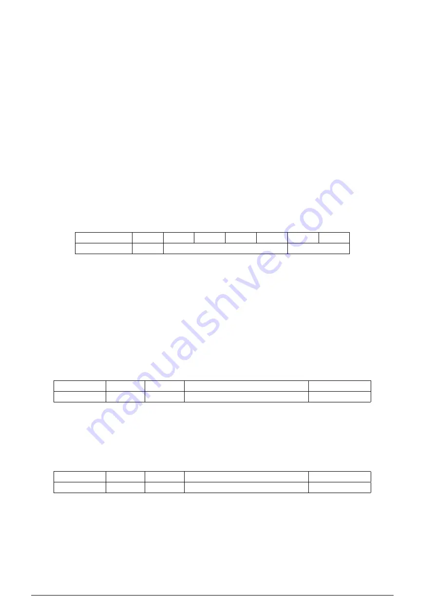
TPDO1 data format

Position and speed data are mapped in TPDO1 as shown in the following figure.

COB-ID 

DLC

D0 

D1

D2

D3

D4

D5

180h + Node-ID

6

Position value

Speed value

Figure 6 - TPDO1 mapped data

  The position data is expressed with a fixed resolution corresponding to 100 μm, in INTEGER32 data format. The speed 

data in expressed with a 1mm/s resolution, in INTEGER16 data format. Byte ordering of position and speed data inside 

TPDO1 follows the LSB..MSB ordering scheme.

  Position and speed values are calculated as follows:


Position [μm]= Position value * 100 μm


Speed [mm/s] = Speed value * 1 mm/s

TPDO1 data transmission

The transmission of the Process Data Object is made when the sensor is in Operational state. To start data transmission, 

the master sends the NMT “Start” command, as shown in the following figure.

Source 

COB-ID

DLC 

Data

Destination

Controller

000h

02h

01h; 

00h*

Sensor

Figure 7 - NMT “Start” command

* 00h: all nodes, nnh: only the node with Node-ID equal to nnh

  To stop data transmission the master sends the “Enter NMT Pre-operational state” command, as shown in the following 

figure.

Source 

COB-ID

DLC 

Data

Destination

Controller

000h

02h

80h; 

00h*

Sensor

Figure 8 - NMT “Enter NMT pre-operational” command

* 00h: all nodes, nnh: only the node with Node-ID equal to nnh

Содержание RK-5 C

Страница 1: ...on services 6 3 3 LSS inquiry services 8 3 4 LSS identification services 10 4 SDO Services page 12 4 1 Object Dictionary 14 4 2 SDO Objects 16 5 PDO Services page 30 5 1 PDO Message Format 30 5 2 PDO...

Страница 2: ...ation is mandatory if at least one of these conditions is true 1 The Node ID of the GEFRAN RK5C sensor is identical to the Node ID of another CANopen device connected to the CAN bus 2 The GEFRAN RK5C...

Страница 3: ...ameters section for details If the value is 1 means that the bit timing is not supported the command was not accepted Storing configuration settings To save the previously configured Node ID and Baud...

Страница 4: ...CANopen position sensor provides one Transmit PDO TPDO1 that includes position and speed data measured by the sensor TPDO1 data format Position and speed data are mapped in TPDO1 as shown in the follo...

Страница 5: ...7E5h Rx 8 D0 D1 D2 D3 D4 D5 D6 D7 04h 00h 00h 00h 00h 00h 00h 00h Figure 10 LSS switch state global waiting state message LSS switch state selective By means of this service the LSS master device swit...

Страница 6: ...ID of the LSS slave device The LSS slave device confirms the success or the failure of the service execution The allowed node ID values are in the range 1 127 01h 7Fh The LSS master sends this messag...

Страница 7: ...active only after the master sends the LSS activate bit timing parameter service or with the next power on after the execution of the LSS store configuration service The bit rate is not automatically...

Страница 8: ...SS store configuration message where Error code 00h Protocol successfully completed or 02h Storage media access error 3 3 LSS INQUIRY SERVICES LSS inquire node ID By means of this service the LSS mast...

Страница 9: ...e sends the response message COB ID Rx Tx DLC Data D0 D1 D2 D3 D4 D5 D6 D7 7E5h Rx 8 5Ch 00h 00h 00h 00h 00h 00h 00h 7E4h Tx 8 5Ch Revision number 00h 00h 00h Figure 20 LSS inquire identity Revision n...

Страница 10: ...e 22 LSS identify remote slave message sequence Where Vendor ID is the LSS slave s identity Vendor ID Intel format byte ordering Product code is the LSS slave s identity Product code Intel format byte...

Страница 11: ...NMT Initialization state owns an invalid FFh pending node ID and no active node ID This service is executed in case a LSS identify non configured remote slave service was initiated by the LSS master...

Страница 12: ...of bytes of Data field Cs 23h 4 transmitted data bytes Cs 27h 3 transmitted data bytes Cs 2Bh 2 transmitted data bytes Cs 2Fh 1 transmitted data bytes Data is the data to be copied in the object dict...

Страница 13: ...bort code explain the reason of the SDO abort event The following table contains the abort codes provided by the protocol SDO abort transfer of the GEFRAN RK5C CANopen device Abort code Description 05...

Страница 14: ...Unsigned8 RO 1 Highest sub index supported 1 Unsigned32 RW 00000001h Writing the signature load 6Ch 6Fh 61h 64h restores all parame ters in flash to their default values 1014h 0 COB ID EMCY Unsigned3...

Страница 15: ...f 0 001 m 2 Unsigned32 RO 100 Speed measuring step given in multiples of 0 01mm s 6010h 0 Preset values for multi sensor devices Unsigned8 RO 1 Highest sub index supported 1 Integer32 RW Preset value...

Страница 16: ...r the GEFRAN RK5C CANopen device two types of error conditions are defined Device hardware error and Data set error The Data Set type error occurs when a mismatch between the stored checksum and the c...

Страница 17: ...atile memory checksum not correct E3 Controller error 0 no error 1 error detected by microcontroller T C temperature state 0 ok C temperature 105 C 1 warning C temperature 105 C Object description Ind...

Страница 18: ...nt to the restricted CAN ID definitions see Restricted CAN ID section A restricted CAN ID cannot be used 1008h Manufacturer device name This object provides the name of the device as given by the manu...

Страница 19: ...ters in non volatile memory 31 0 e 65h v 76h a 61h s 73h MSB LSB Figure 33 Storage write access structure By read access the sub index 1 of this object the device provides information about its saving...

Страница 20: ...bilities Giving the value of 1 it means that the device can restore parameters on command The default values are set valid after the device is power cycled Restore default Power cycle Default values v...

Страница 21: ...user defined 11 bit CAN ID of the CAN base frame Table 5 COB ID EMCY message fields The user can change the default COB ID EMCY value in the range of the allowed values ensuring that no conflicts with...

Страница 22: ...rtbeat time The producer heartbeat time indicates the configured cycle time of the heartbeat given in 1 ms The value 0 disables the producer heartbeat Object description Index Name 1017h Producer hear...

Страница 23: ...dex 2 specify the COB IDs for the first SDO The object structure is specified in the following figure 31 30 29 28 11 10 0 valid dyn frame Reserved 0 0000h 11 bit CAN ID Figure 37 Structure of SDO1 COB...

Страница 24: ...e range of the allowed values ensuring that no conflicts with other COB IDs are generated The value is also automatically changed in accordance with the default scheme when changing the Node ID value...

Страница 25: ...1A00h TPDO1 mapping parameter This object contains the mapping for the PDOs the device is able to transmit Sub index 1 and sub index 2 contain the information of the mapped application objects The obj...

Страница 26: ...Type Value Range Default 0 Operating parameters RO Unsigned16 0000h 0000h This object is not supported by the GEFRAN RK5C CANopen device 6005h Linear encoder measuring step settings This object indica...

Страница 27: ...d by the preset value Using the Restore default parameters see object 1011h the preset value is cancelled i e the offset is set to zero The preset value is not saved in non volatile memory but it can...

Страница 28: ...when the cyclic timer is programmed unequal 0000h and the TPDO1 transmission type is set to 254 or 255 Cyclic timer settings are explained in the following table Value Description 0 Event driven TPDO1...

Страница 29: ...that is an output of the encoder The measuring step is given in mul tiples of 0 001 m This object is similar to the object 6005h sub index 1 Object description Index Name 6501h Measuring step Entry d...

Страница 30: ...n INTEGER32 data type Speed data is an INTEGER16 data type Assuming that the data is expressed as a bit sequence of length 16 for INTEGER16 data type b0 b15 and as a bit sequence of length 32 for INTE...

Страница 31: ...s explained in the following figure COB ID Rx Tx DLC Data D0 D1 D2 D3 D4 D5 D6 D7 PDO COB ID RTR bit Rx 0 Figure 43 RTR message format Asynchronous Transmission The transmission of the PDO is performe...

Страница 32: ...is not allowed Operational state In the operational state all communication objects are active Object Dictionary Access via SDO is possible and the node can handle PDO communication Stopped state In t...

Страница 33: ...on Reset communication Pre operational Operational Stopped PDO X SDO X X Boot up X SYNC X X EMCY X X NMT error control Heartbeat X X X NMT node control X X Table 10 NMT states and communication object...

Страница 34: ...005h SYNC COB ID 9 EMCY SERVICES Emergency objects are triggered by the occurrence of the CANopen device internal error situation An emergency object is transmitted only once per error event No furthe...

Страница 35: ...he heartbeat consumer aware of this heartbeat message will be informed about that event The format of the heartbeat message is explained in the following figure COB ID Rx Tx DLC Data D0 D1 D2 D3 D4 D5...

Отзывы: