


17
9. Working with road car OBDII On-Board Diagnostics
All passenger cars for public road use manufactured after 1992 are fitted with an on-board diagnostics port. This
port is used to transmit real-time engine parameters relating to emissions control. Whilst some of these
parameters are of little importance to us in a motorsport context, there are many other parameters available to
read that are of interest to us. The Geartronics G-Dash is able to read and display all available ODBII parameters
providing that the vehicle complies with the ISO 15765-4 CAN based standard. This protocol is used in most
modern road cars.
Note: older implementations of OBD using the K-line interface are not supported.
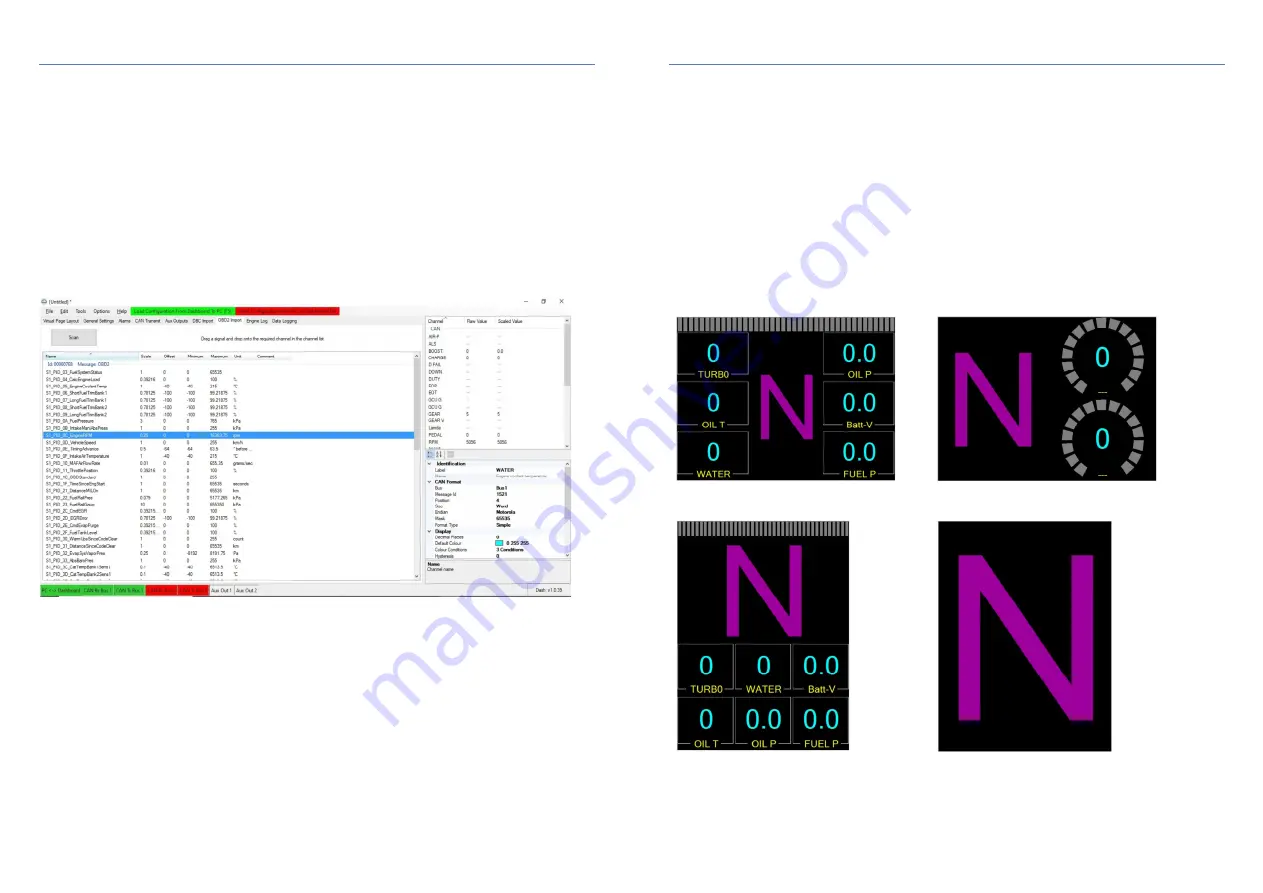
To setup the OBD communication, select “OBD2 Import” tab and then click the “Scan” box at the top left of the
screen. This will send a series of interrogation messages to the ECU to request a list of available channels. If the
dashboard receives a response from the ECU it will then list all channels that your ECU has available for
transmission, including their PID (Parameter ID) and scaling information etc.
Note: If the dashboard does not
receive a response from the ECU then you will be prompted to load a list of all standard OBD channels, some of
which will not be available to read from your specific ECU.
When you have a list of channels in the main window
you can then drag & drop channels from this list onto the appropriate dashboard channel on the right hand side of
the page. If the OBD channel that you want to display is not already in the list then right-click anywhere within the
channel list window and select “New Custom Channel”. You can then rename it using the channel properties
underneath.
Note that OBDII uses a request/response protocol, not a ‘broadcast’ protocol, In other words, the channel values
are not constantly transmitted on the CAN bus for any device to read. Instead, we must request specific data from
the ECU by use of special request messages sent from the dashboard.
When you drag and drop a channel onto the list on the right hand side, all the CAN parameters are automatically
populated to enable the dash to transmit the appropriate request message. The only parameter that you may
need to adjust is the “OBD Interval”. This is the frequency at which the channel data is requested from the ECU.
The default value is 10Hz, but you may want adjust this to suit the type of data you wish to read. For example,
there is little point in requesting engine temperature data 100 times per second because temperatures do not
change that rapidly. In this example, 10Hz will be adequate. On the other hand engine RPM can change very
rapidly, so you may wish to read this channel at 50Hz. Always select the lowest OBD Interval necessary to avoid
‘flooding’ the CAN bus with unnecessary messages. Note: if the OBD interval is set to 1Hz and the ECU fails to
respond to the request, or the message is ‘dropped’ by the bus, then the dash may fail to display any data until a
reply is received to the next request message. This is due to the timeout period of the CAN bus.
18
10. General settings tab
10.1 CAN speed
The CAN receive and transmit speed can be set individually for each of the two CAN channels. This feature
can be useful if the dash is used as a ‘bridge’ between 2 CAN buses that are running at different speeds.
However, most installations will probably use only the CAN1 channel on the main 14-pin connector.
The dashboard supports bus speeds of 125-kbit/s, 250-kbit/s, 500-kbit/s and 1-mbit/s. Most aftermarket
ECUs have a CAN speed of 1-mbit/s. Most OEM road car ECUs (including the OBDII diagnostic port) run at
500-kbit/s.
10.2 Display orientation
Unlike most other motorsport display systems, the Geartronics G-Dash is able to operate in both landscape
or portrait modes. It is envisaged that landscape will be the most common configuration, but portrait mode
is useful if the dash is to be used primarily as a gear indicator during competition. In this mode, a page can
be added (Portrait 2) to show only a full-screen gear number. Some typical page formats are shown below.


