GEARTRONICS G-Dash Colour Dashboard Скачать руководство пользователя страница 8

15 


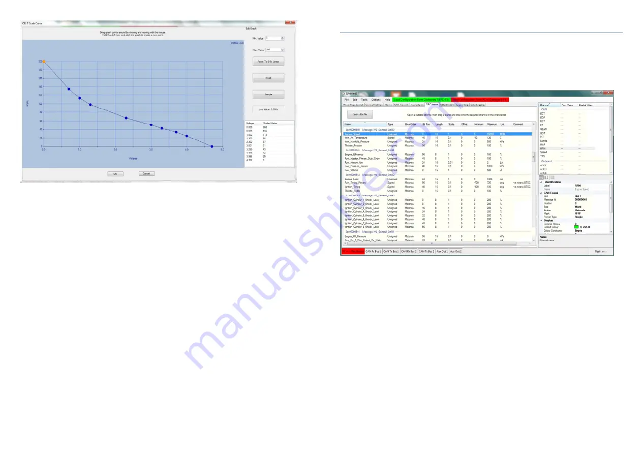
The scaling graph may include up to 10 sample points, which is sufficient for the vast majority of 
applications. The default graph contains just two points with a straight line drawn between them. The dash 
automatically interpolates between points. To add more sample points, hold the shift key and then click 
anywhere in the graph area. To manually move points, simply click the point and drag to the desired 
position. It’s also possible to sample the live value currently being read from the sensor, or to enter values 
manually (usually from sensor manufacturer data) in the table at the bottom right of the screen. 

Note: when using the sample function you must have already sent a valid configuration to the dash so that 
it knows which input to read. 


16 


8. Working with .dbc files 

To  save  considerable  time  in  setting  up  CAN  channels,  it  may  be  possible  to  obtain  a  CAN  database  file  from 
your ECU supplier. This is a special text file that has a .dbc filename extension. The .dbc file uses a standardised 
format that the G-Dash software can read. The database file contains all the configuration information required to 
setup CAN channels without the need to enter any parameters manually.  
 
To use a .dbc file, select the “DBC Import” tab at the top of the main window and click on the grey box at the top 
left – “Open .dbc file”. 


To  configure  a  channel  simply  drag  &  drop  the  desired  channel  from  the  list  in  the  main  window  onto  the 
appropriate  dashboard  channel  in  the  list  on  the  right  of  the  screen.  All  the  CAN  properties  for  that  particular 
channel  are  then  automatically  populated.  If the channel  you wish  to  add  is  not present  in  the  list of dashboard 
channels then right click in the top right hand window and select “New Custom Channel”. In the example above, a 
MoTeC M1 “Engine Speed” channel has been mapped to the RPM channel on the dashboard. Continue to drag 
and drop channels until all desired dash channels have been configured. The dash does not need to be on-line 
during the configuration process, but you will need to save the configuration and send it to the dash the next time 
you connect. 


Содержание G-Dash Colour Dashboard

Страница 1: ...e 12 o 7 4 Display properties Page 13 o 7 5 Display colours Page 13 o 7 6 Display limits Page 14 o 7 7 CAN data scaling Page 14 o 7 8 Configuring analogue input channels Page 14 o 7 9 Analogue scaling...

Страница 2: ...2 x common pre defined channels such as RPM water temp oil temp oil pressure etc Up to 10 additional user defined custom CAN channels Up to 5 analogue channels 0 5v Linear or non linear analogue input...

Страница 3: ...location to either side is acceptable Although the TFT display has a very wide viewing angle when mounted to one side it s recommended that the unit is angled towards the driver Optional mounting kit...

Страница 4: ...xist then check through the Device Manager list looking for any unknown device that has a yellow triangle beside it This signifies that Windows knows that a device is connected but has failed to insta...

Страница 5: ...file This makes dashboard channel setup a quick and simple task Click on the Import DBC file box or select Tools Import from DBC Further information can be found in section 8 of this user manual OBD2...

Страница 6: ...nnel You can then rename the channel label to how you would like it to appear on the dash Keep the label as short as possible due to space limitations We recommend that labels for text display values...

Страница 7: ...as half way around the gauge For example the normal engine coolant temperature may be 80 C but the ECU might transmit values between 20 and 200 Therefore we can set the display limits between 40 and...

Страница 8: ...bc filename extension The dbc file uses a standardised format that the G Dash software can read The database file contains all the configuration information required to setup CAN channels without the...

Страница 9: ...e of special request messages sent from the dashboard When you drag and drop a channel onto the list on the right hand side all the CAN parameters are automatically populated to enable the dash to tra...

Страница 10: ...value before you can add a new gear Alternatively you can sample the current value from the gear channel by clicking the Sample box After the value is entered you can add a new gear and rename it as r...

Страница 11: ...is triggers a warning message to flash up when a channel value falls outside of the acceptable range Multiple alarms are supported and are displayed in sequence The time each alarm is visible in the s...

Страница 12: ...en circuit when not active and switched to ground when active They are capable of switching loads up to 2 Amps with a supply voltage up to 12v Note when connecting to digital inputs of other devices i...

Страница 13: ...Intel To add data channels to the message frame move to the lower half of the window and you will see a list of 8 slots representing the 8 bytes of the message frame The top slot in the list represent...

Страница 14: ...ddition to the engine log and the recording of maximum channel values the Geartronics G Dash has full on board data recording capability Retrieved data is viewed graphically in our own Dashview data a...

Страница 15: ...from the standard Windows palette Scaling Min minimum displayed value Scaling Max maximum displayed value Filter used for smoothing a noisy trace Show Samples changes the trace from an interpolated li...

Страница 16: ...ely 120ohms Incidentally when the bus is terminated correctly with 2 resistors you will measure approximately 60ohms when you conduct this test 32 The dashboard is supplied with the CAN terminators sw...

Отзывы: