


11
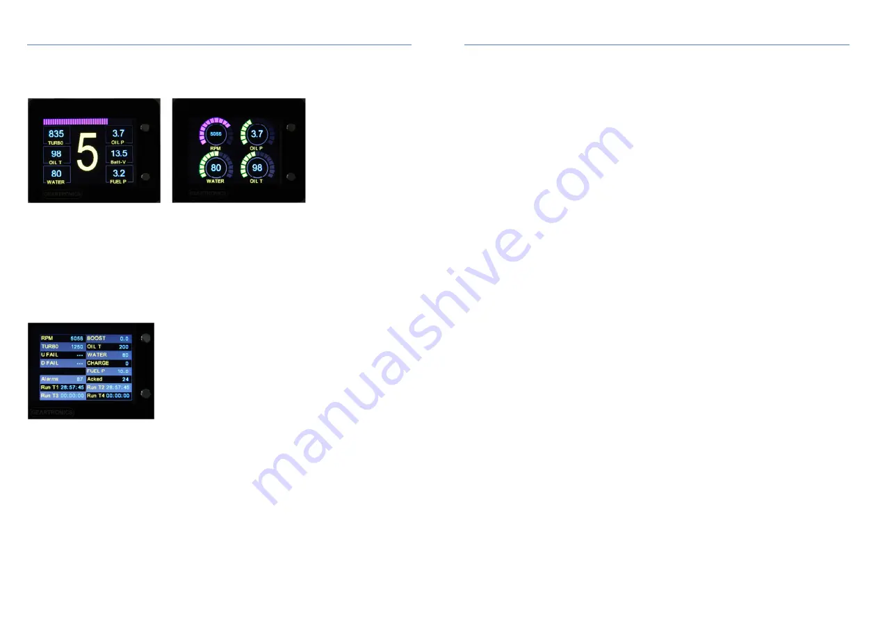
6. Adding display pages
The G-Dash software allows the addition and configuration of multiple pages which are sequentially scrolled using the
top button on the front panel of the dash (right button if used in portrait mode). There are nine predefined data page
layouts plus a ‘tell-tale’ page that displays the maximum recorded values of selected channels. Data channels can be
displayed in either text format or as dial gauges, two examples of which are shown below:
To add a page, select the “Virtual Page Layout” tab and right click in the left hand margin. It is recommended that you
add as few pages as necessary so as to avoid the need to scroll through multiple pages. For most applications, 3 or 4
pages is usually sufficient. You can reorder the sequence of the pages by dragging and dropping them to different
positions in the left hand margin after they have been added. To delete a page, simply right click and select delete.
Note that “Landscape 1” and “Portrait 1” pages feature an ‘RPM bar’ along the top, the colour of which is configurable
depending on engine speed. To set the RPM band colours, use the colour conditions option for the RPM channel.
In addition to the usual data pages, users may also add a ‘tell-tale’ page (Landscape10) that can be accessed by
holding the page select (top button) during power up. This page will display the maximum recorded values of the
selected channels since last reset. These values may be reset either by pressing and holding the page button for 2
seconds (while the page is being viewed) or by selecting “Reset Stats” from the “Engine Log” page of the software.
To exit the tell-tale page without clearing the maximum values, press the page button briefly to return to the main
display pages.
6.1 Adding channels to pages
After pages have been added to the Virtual Page Layout, you can then start to add data channels to each of the
pages. To do this, simply drag and drop channels from the channel list at the top of the right hand window onto the
required position on the virtual page in the centre of the screen. Any channels (CAN or analogue) may be placed on
any page. The same channel may also be added to multiple pages if desired.
Note: You can add channels to pages before the communication parameters have been set. However, the channel
properties must be fully configured in the lower right-hand window before the dashboard can display any live data
values.
12
7. Adding & Configuring data channels
7.1 Adding & renaming channels
The G-Dash software has a predefined list of 12 commonly used CAN data channels that will cover
most applications. However, if necessary, up to ten additional custom CAN channels may be added to
the list. The predefined channels may also be renamed to suit individual requirements.
To add a new channel, right-click in the channel list window (top right) and select “New Custom
Channel”. You can then rename the channel label to how you would like it to appear on the dash.
Keep the label as short as possible due to space limitations. We recommend that labels for text
display values (page style 1) are kept to 10 characters maximum, and 6 characters for dial gauge
values (page style 3-9). If you wish to include the degree (°) symbol then please use the ~ character.
Note that the channel name is greyed out and cannot be changed. Only the channel label, which is the
text displayed on the dash, may be changed.
7.2 Configuring channels
Data channels may take their source either from the CAN bus or one of the five analogue inputs (AN1-5).
When using CAN, it is assumed that users will have a basic working knowledge of CAN protocol setup. In
all cases you will need the CAN template from your ECU supplier, or be familiar with the CAN transmit
configuration of your ECU. Alternatively, you can import a CAN database file to simplify CAN setup. The
.dbc file is the best option as it will save a lot of manual configuration, but not all manufacturers supply one
for their ECUs. For more information on .dbc setup please see section 8 of this manual.
If the dash is to be connected to a road car ECU using the OBDII diagnostic connector then please see
section 9 of this manual for channel configuration information.
Note: A help box is provided at the bottom of the channel configuration window that provides a detailed
description of the parameter that is currently highlighted.
7.3 Manual CAN setup
To configure a CAN channel, click on the channel name at the top of the right hand window. Underneath
this window is a list of CAN parameters as follows:
•
Bus
– Selects which of the two CAN ports to use (most installations will use only CAN-1)
•
Message Id
– specifies the message address in either hex or decimal format (the format is selected
under the options menu at the top of the screen)
•
Position
– specifies the start location of the data within the 8-byte CAN frame (0 is the first byte)
•
Size
– specifies either 8-bit Byte or 16-bit Word. Signed bytes and words are used to display
negative values. Most aftermarket ECUs tend to use 16-bit words to transmit all channels, therefore
it’s usual for each message to contain up to 4 channels of data.
•
Endian
– specifies the most significant byte of a 16-bit (2 byte) channel. Most common is Motorola
format, but some ECUs (DTA for example) use Intel format.
•
Mask
– allows individual bits to be read. Used if the channel data occupies only part of a byte. For
example, some OEM road car ECUs occasionally use only 4 bits of a byte for some channels that
only require low resolution. Normally the mask is set to FFFF (65535)
•
Format type
– Specifies either simple addressing or compound (multiplexed) addressing.
Multiplexed addressing is used when the same CAN Id is used to transmit multiple channels of data.
In this case, the first byte or word of the frame is used to transmit a frame identifier. This is often
used by OEMs to ‘hide’ data and prevent it from being easily read and de-coded using simple CAN
sniffing tools.


