


19
10.3 On-Board Tacho
In the unlikely event that the engine speed cannot be read from the CAN data stream then it’s possible to
measure a conventional tacho pulse signal from the ECU by connecting to an analogue input. However, it
is only possible to measure 5v signals.
You must not connect a 12v tacho signal to any of the AN inputs, or make a connection directly to the
ignition coil(s) as this will immediately damage the dashboard!
Inputs AN1-4 may be used to measure tacho pulses. It is not possible to use AN5. If the ECU tacho output
is an open-collector or open-drain output then it will be necessary to connect a 1Kohm pull-up resistor
between the input and the sensor 5v supply on pin 10.
When connecting to a tacho pulse signal you must change the “RPM sensor type” from CAN to
“Onboard_Tacho”, and also specify the number of pulses per 2 revolutions of the engine – this is usually
the same as the number of cylinders (i.e. 1 pulse per spark), but some ECU’s may be configured differently.
10.4 Vehicle speed measurement
Vehicle speed is usually measured from the CAN data stream, but in the absence of this channel the
dashboard can be configured to measure the speed using a standard hall-effect wheel-speed sensor taken
from an un-driven wheel. Inputs AN1-4 may be used to connect wheel-speed sensors. It is not possible to
use AN5. When using a wheel-speed sensor it’s necessary to enter the exact tyre circumference (in mm)
and the number of sensing ‘teeth’ on the wheel hub.
Speed may be displayed in either miles per hour (MPH) or kilometres per hour (KPH).
10.5 Gear indicator configuration.
The gear indicator may take its source either from the CANbus or a 0-5v gear position sensor connected to
the AN1 analogue input. If your vehicle has a H-pattern gearbox, it’s still possible to display the selected
gear. This is done by comparing the engine speed with road speed to calculate the ratio and compare with
programmed or sampled ratios.
The “Gear sensor type” can be set to the following options:
•
CAN
•
Onboard_ADC
•
Calculated
When using CAN or a direct sensor connection, you must populate and configure the gear table at the top
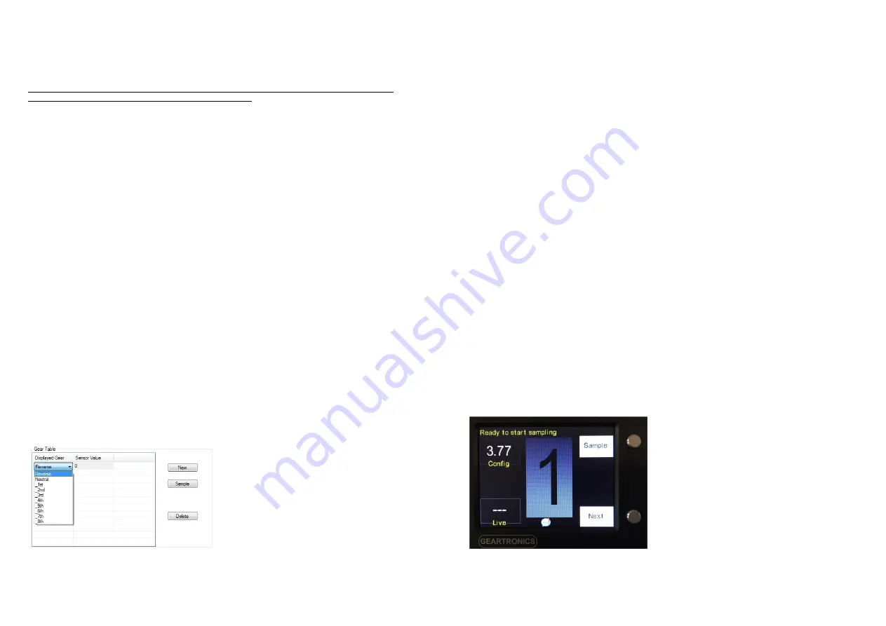
of the general Settings page. First of all, assuming the table is blank, click “New”. Reverse gear will be
added to row 1 of the table. To change the gear number, click on the gear and then select a new gear from
the drop-down list as shown below.
20
If the first “Displayed Gear” in the table is reverse, you must manually enter a non-zero value before you
can add a new gear. Alternatively you can sample the current value from the gear channel by clicking the
“Sample” box. After the value is entered, you can add a new gear and rename it as required, again entering
or sampling a value before adding the next gear. Continue in this fashion until the table is populated with all
your gears, up to a maximum of 8.
Note that gear sampling can only be done after the gear channel has been set up and a valid configuration
sent to the dash.
The “Gear Tolerance” must be set to an appropriate value so that each gear is reliably detected and
displayed. Sensor readings outside of this tolerance will be treated as ‘unknown’ and a horizontal dash will
be displayed.
10.6 Calculated gear number
For vehicles fitted with H-pattern gearboxes, or sequential gearboxes where no gear position sensor is
available, it may still possible to display the selected gear. However, in order for the dashboard to calculate
the gear number, both the engine speed and vehicle ground speed must be available.
Note: the gear number calculation can only be made when there is a direct link between engine and driven
wheels – in other words, when a forward gear is selected and the clutch engaged. It is not possible to
calculate the gear when the clutch is disengaged or if neutral is selected.
To use this function, first set the Gear Sensor Type to “Calculated”. Next, populate the gear table, starting
with neutral and then all forward gears. If you know the gear ratios, enter these into the sensor value
column of the table. If you do not know the actual gear ratios then initially enter any positive values into the
sensor value column. In any event, you must enter a value of 0 for neutral.
Enter the final drive ratio (if known) in the “Speed Calculation” settings. If both the final drive and gear ratios
are known and entered correctly then the gear indicator should now be able to accurately calculate the
selected gear providing that the engine RPM and vehicle speed are being read correctly. However, if the
ratios are not known then the dashboard must be put into a ‘Gear Sample’ mode in order to learn the ratio
of each gear. In this case, you must still enter a value for the final drive, even if the exact value is not
known. We recommend setting it to 3 or 4.
Note: In order to learn the gear ratios it’s necessary to drive the vehicle at a constant speed in each gear.
Gear learning can only be done on the road or track, unless the vehicle speed is being derived from a
driven wheel.
To start the gear learning routine, press and hold the alarm button while powering the dashboard on. After
a short while the following screen will be displayed:


