GEARTRONICS G-Dash Colour Dashboard Скачать руководство пользователя страница 4


4. Software & driver installation 

4.1 G-Dash software installation 

 
The latest Geartronics G-Dash software can be downloaded from here: 

www.geartronics.co.uk/files/gdash.zip


When the zip file has downloaded, extract the two files from within the zip file and copy to a new folder. Run the 
‘setup.exe’  executable  file  and  follow  the  instructions  on  screen.  You  may  need  to  be  logged  on  as  an 
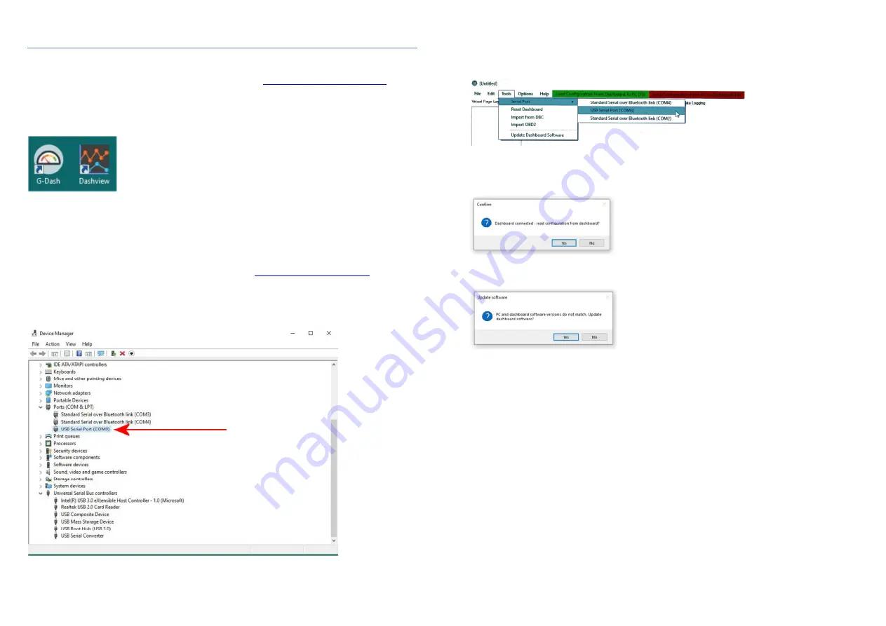
administrator user in order to do this. After installation, two icons will be placed on your desktop: the main G-Dash 
software, and also the Dashview data logging software as shown below. 


4.2 Windows device driver installation


Laptop PC connection to the dashboard is via a standard  micro  USB port on the bottom of the unit. Note: Only 
use the USB cable supplied with the dashboard as some phone charger cables do not include the data wires and 
will therefore not work. Before the software can communicate with the dashboard it’s necessary to install the USB 
Windows device drivers. Newer laptops running Windows 8 or 10 should already have native support for the FTDI 
USB chip in the dashboard, and your laptop should recognise and setup a ‘virtual’ COM port as soon as the dash 
is connected and powered  on. However,  if  you  have difficulty  in connecting  to  your  dashboard  then you should 
download and install the latest device drivers from the FTDI website: 

www.ftdichip.com/Drivers/VCP.htm


To  verify correct  driver  installation,  go  to Windows  “Device  Manager”,  expand  the  “Ports”  list  and  check  for  the 
presence  of  a  “USB Serial  Port”.  If no COM ports exist  then  check  through the  Device  Manager  list,  looking for 
any  unknown  device  that  has  a  yellow  triangle  beside  it.  This  signifies  that  Windows  knows  that  a  device  is 
connected but has failed to install the necessary drivers.   


4.3 Initial software connection 

 
With the dashboard connected and powered on, launch the G-Dash software from the desktop and click “Tools” 
from  the  menu  bar  at  the  top  of  the  screen,  then  click  “Serial  Port”.  Select  the  appropriate  COM  port  from  the 
drop-down list.  


If  connection  is  successful  then  you  will  be  presented  with  a  dialogue  box  asking  if  you  would  like  to  read  the 
current configuration. Under normal circumstances you should answer “Yes” unless you intend to send a different 
configuration to the dashboard. 


Note:  If  you  have  downloaded  the  latest  G-Dash  software  from  the  Geartronics  website  and  you  connect  to  a 
dashboard with an earlier firmware version then you will first be asked if you want to update the firmware.  


When  updating  firmware,  it’s  very  important  that  nothing  interrupts  the  update  process  as  this  can  corrupt  the 
dashboard  memory  and  render  the  unit  inoperable  until  it  can  be  factory  reprogrammed.  It  is  therefore  not 
recommended that firmware updates are performed at the track or immediately before a track test or race. Before 
performing a firmware update ensure that you have the current configuration saved to disk as this will need to be 
sent back to the dash after the update has completed. 

 
Unless requested otherwise, the unit is shipped with a base configuration with a single page displaying the most 
common engine parameters. However, until these channels have been fully set up in either the CAN or analogue 
configuration the dash will not display any ‘live’ data. 


Содержание G-Dash Colour Dashboard

Страница 1: ...e 12 o 7 4 Display properties Page 13 o 7 5 Display colours Page 13 o 7 6 Display limits Page 14 o 7 7 CAN data scaling Page 14 o 7 8 Configuring analogue input channels Page 14 o 7 9 Analogue scaling...

Страница 2: ...2 x common pre defined channels such as RPM water temp oil temp oil pressure etc Up to 10 additional user defined custom CAN channels Up to 5 analogue channels 0 5v Linear or non linear analogue input...

Страница 3: ...location to either side is acceptable Although the TFT display has a very wide viewing angle when mounted to one side it s recommended that the unit is angled towards the driver Optional mounting kit...

Страница 4: ...xist then check through the Device Manager list looking for any unknown device that has a yellow triangle beside it This signifies that Windows knows that a device is connected but has failed to insta...

Страница 5: ...file This makes dashboard channel setup a quick and simple task Click on the Import DBC file box or select Tools Import from DBC Further information can be found in section 8 of this user manual OBD2...

Страница 6: ...nnel You can then rename the channel label to how you would like it to appear on the dash Keep the label as short as possible due to space limitations We recommend that labels for text display values...

Страница 7: ...as half way around the gauge For example the normal engine coolant temperature may be 80 C but the ECU might transmit values between 20 and 200 Therefore we can set the display limits between 40 and...

Страница 8: ...bc filename extension The dbc file uses a standardised format that the G Dash software can read The database file contains all the configuration information required to setup CAN channels without the...

Страница 9: ...e of special request messages sent from the dashboard When you drag and drop a channel onto the list on the right hand side all the CAN parameters are automatically populated to enable the dash to tra...

Страница 10: ...value before you can add a new gear Alternatively you can sample the current value from the gear channel by clicking the Sample box After the value is entered you can add a new gear and rename it as r...

Страница 11: ...is triggers a warning message to flash up when a channel value falls outside of the acceptable range Multiple alarms are supported and are displayed in sequence The time each alarm is visible in the s...

Страница 12: ...en circuit when not active and switched to ground when active They are capable of switching loads up to 2 Amps with a supply voltage up to 12v Note when connecting to digital inputs of other devices i...

Страница 13: ...Intel To add data channels to the message frame move to the lower half of the window and you will see a list of 8 slots representing the 8 bytes of the message frame The top slot in the list represent...

Страница 14: ...ddition to the engine log and the recording of maximum channel values the Geartronics G Dash has full on board data recording capability Retrieved data is viewed graphically in our own Dashview data a...

Страница 15: ...from the standard Windows palette Scaling Min minimum displayed value Scaling Max maximum displayed value Filter used for smoothing a noisy trace Show Samples changes the trace from an interpolated li...

Страница 16: ...ely 120ohms Incidentally when the bus is terminated correctly with 2 resistors you will measure approximately 60ohms when you conduct this test 32 The dashboard is supplied with the CAN terminators sw...

Отзывы: