background image

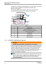
Packaged base frame:

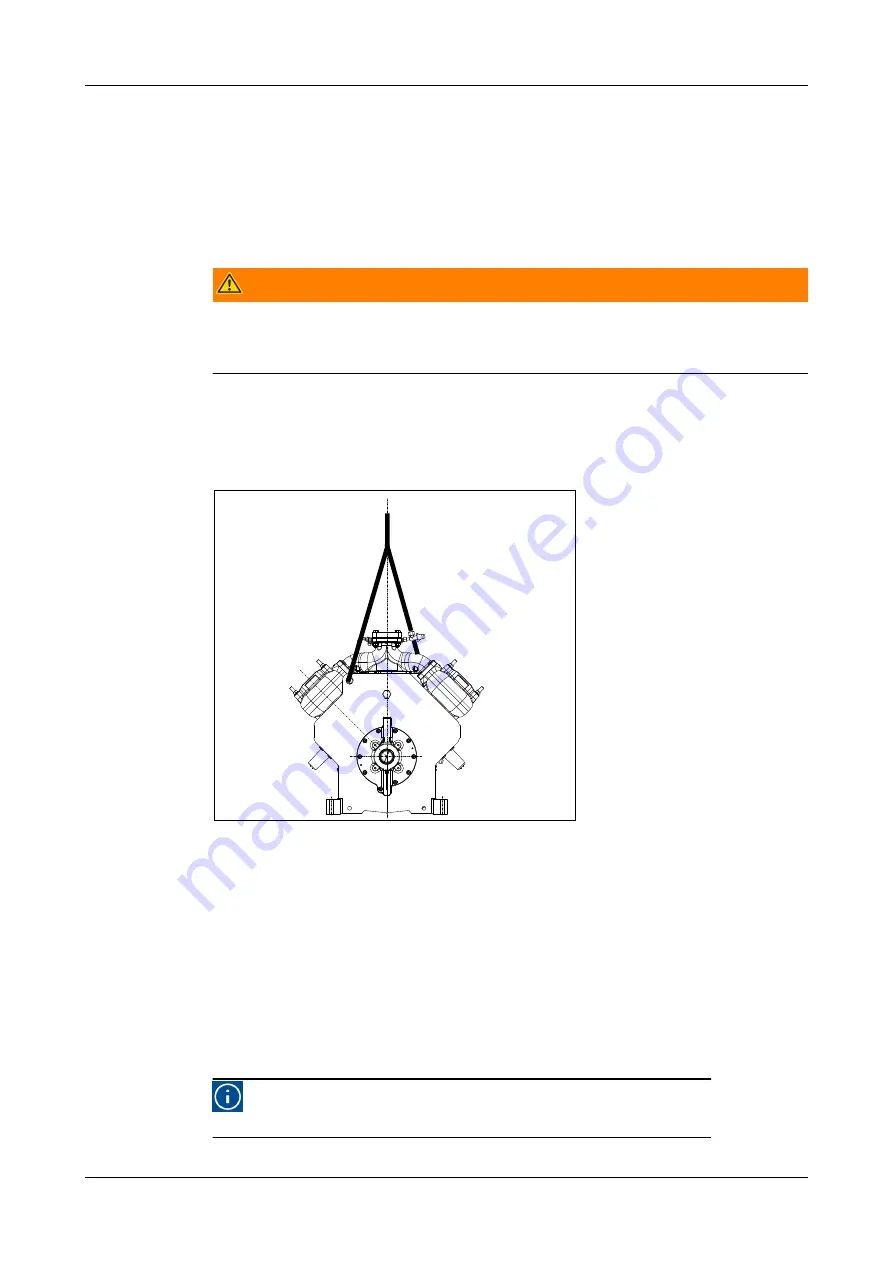
The only places that can be used for safe hoisting of the package are the four
hoisting eyes on the steel base frame as shown in the above figure. Prior to
hoisting a compressor package with a V-belt drive arrangement, the factory
mounted drive guard has to be removed. Attach spreader bars to the slings so as
to prevent damage to piping and components.

Warning!


DO NOT use the compressor or motor or oil separator hoisting eyes to
move the package! These hoisting eyes are intended for lifting loose
components only and not for the entire package!

Bare compressor or loose components:

Determine the dead weight of the particular component (see "Product Information
(ED)"), prior to moving a bare compressor or loose component. Use the hoisting
eyes only, DO NOT sling from other compressor parts (see Figure 3, Page 15).

Fig.3:

Hoisting angle

Moving by fork-lift truck

The bare compressor or package can be transported with a fork-lift truck with the
forks spread as much as possible between the skids. To simplify moving, the 2
wooden transport beams must still be mounted underneath the base frame and
stored in this way, until the package is positioned above its approximate location.

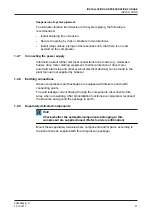
1.2.4

Required free space

For easy operating, servicing and maintenance access, the compressor
(package) should be installed with sufficient free space around it.

Hint!

Refer to “Product Information“ for minimum requirements.

INSTALLATION AND PREPARATION FOR USE

INSTALLATION

0089288gbr_11


30.10.2017

15

Содержание Grasso V 1100

Страница 1: ...Reciprocating Compressors for industrial refrigeration GEA Grasso V Installation and Maintenance instructions 0089288gbr_11 ...

Страница 2: ... or otherwise without prior written consent of GEA This restriction also applies to the corresponding drawings and diagrams LEGAL NOTICE This publication has been written in good faith However GEA cannot be held responsible neither for any errors occurring in this publication nor for their consequences 0089288gbr_11 2 30 10 2017 ...

Страница 3: ...IONS Hint This manual must be carefull read and understood prior to installing and servicing the compressor package Safety This manual is written with great care but the contractor installer is held responsible to examine this information and to take care of possible additional and or deviated safety measures Safety instructions It is the task of the contractor installer to inform and explain to h...

Страница 4: ...re keep the compressor closed until the compressor package is being installed Warning The compressor is not filled with oil Hint After the successful initial run of the compressor package the warranty chart must be filled in and returned to Grasso A warranty chart is attached to each compressor 0089288gbr_11 4 30 10 2017 ...

Страница 5: ...s mentioned in this manual For instance not all compressor series are suitable for all mentioned refrigerants or not all compressor series includes two stage compressors Directives Equipment is based on Pressure Equipment Directive PED 97 23 EG regulations and according to Machine Directive MD 2006 42 EG regulations The applied standards are NEN EN IEC 60204 NEN EN ISO 12100 NEN EN ISO 13857 NEN E...

Страница 6: ...0089288gbr_11 6 30 10 2017 ...

Страница 7: ...ylinder numbering Fig 1 Example cylinder numbering 6 cylinder compressor Booster or single stage operation 1 Booster operation applies if condensing temperature 5 oC 2 Single stage operation applies if condensing temperature 5 oC 0089288gbr_11 30 10 2017 7 ...

Страница 8: ...0089288gbr_11 8 30 10 2017 ...

Страница 9: ...sor is allowed to be started Max oil temperature Refer to oil selection table applied type of oil Required oil viscosity 10 cSt during operation at location of bearings The maximum temp depends on the operating conditions of the compressor the oil type used and A minimum actual oil viscosity of 10 cSt in the bearings is always requried bearing temp to determine oil viscosity is approx oil temperat...

Страница 10: ...0089288gbr_11 10 30 10 2017 ...

Страница 11: ...nitial oil warm up 27 1 3 9 Initial start up 27 Limitations of part load operation and start up 27 WIRING LOGIC NORMALLY OPEN UNLOADED START SOLENOID 27 Frequency controlled compressor 28 Pre start check list 28 1 3 10 Starting and stopping procedures 28 First start 28 Restart 29 Restart after a short standstill period of time less than 1 month 29 Restart after a long standstill period of time 29 ...

Страница 12: ...ENDIX Product Information PI 50 4 1 GRASSO MAINTENANCE MONITOR 50 4 2 GENERAL LIMITS OF OPERATION GRASSO V 51 4 3 STARTING UP OF TWO STAGE COMPRESSORS 52 4 4 DIAGRAMS SINGLE STAGE AND BOOSTER 54 4 5 DIAGRAMS TWO STAGE 55 4 6 LUBRICATING OILS choice and recommendations 58 4 6 1 STRONGLY RECOMMENDED OIL TYPES 58 4 6 2 ACCEPTED NH3 OIL TYPES 59 4 7 Pre lubrication oil system 60 0089288gbr_11 12 30 10...

Страница 13: ...the compressor package is ready for the initial start up the installation instructions in the following paragraphs must be followed 1 The Compressor Package should be levelled and securely anchored to the foundation 2 All piping should be completed 3 The system and the compressor are to be pressure tested for leaks see Section 1 3 1 Page 22 4 The system should be evacuated to remove air and moistu...

Страница 14: ...e Product Information Caution Every precaution must be taken while moving the package to its final location Pushing pulling or climbing on any package component or piping can easily create damage 1 2 2 Storage The compressor package is filled with dry nitrogen Keep the system closed until the package is installed If the compressor package is stored it should be kept at all times in a dry location ...

Страница 15: ...ular component see Product Information ED prior to moving a bare compressor or loose component Use the hoisting eyes only DO NOT sling from other compressor parts see Figure 3 Page 15 Fig 3 Hoisting angle Moving by fork lift truck The bare compressor or package can be transported with a fork lift truck with the forks spread as much as possible between the skids To simplify moving the 2 wooden tran...

Страница 16: ...age 19 Section Page 19 1 b Frame designed for mounting on vibration dampers For more details in case mounting base frames on vibration dampers is applied refer to separate instruction sheet and other order documentation like package drawing supplied with the compressor package and consult Grasso if required 2 Bare compressor direct mounted on a concrete block via grouted anchors For more installat...

Страница 17: ...ended to consult a concrete specialist constructor for the following items The compound of the concrete with without reinforcement The exact grouting depth dependent on the soil conditions Installing foundation onto an existing floor with sealing corkboard or vibration isolators 1 2 5 2 Anchoring After the concrete block has cured the anchors should be installed as shown above and in case of a pac...

Страница 18: ...ing the base frame base frame cannot be removed easily 3 Drilling angle 1 2 5 3 Mounting the base frame on a concrete block General After the space between base frame and concrete base has been filled up with a filling grout the package base frame must be secured tightly to the foundation block or floor INSTALLATION AND PREPARATION FOR USE INSTALLATION 0089288gbr_11 18 30 10 2017 ...

Страница 19: ...rtar supplier Finishing with a self levelling grout After levelling has been completed the adjusting bolt ends must be greased to avoid bonding to the self levelling grout The space between concrete block and frame must be completely filled with the self levelling grout to ensure that the complete bottom surface of the base frame will be supported Therefore it is not allowed to use shims between c...

Страница 20: ... Width of compressor foot WL WC 40 mm 1 2 6 Connecting to refrigerating system pipework Warning DO NOT ground through the compressor when arc welding After the compressor package has been levelled and secured to the foundation the system piping may be connected The suction line s and discharge line s should be installed and supported such that there is no load exerted on the compressor The size an...

Страница 21: ...can be found in the plant manual not supplied by Grasso 1 2 8 Earthing connections Grasso compressors and packages are equipped with litz wires and earth connecting points To avoid leakage current flowing through the components disconnect all litz wires when arc welding After all installation functions are completed reconnect the litz wires and ground the package to earth 1 2 9 Separately delivere...

Страница 22: ...maining 18 hours 1 3 2 EVACUATION DRYING THE REFRIGERATING SYSTEM For evacuation of compressor only refer to Section 2 5 Page 33 Procedure to evacuate and to dry a system i STATUS System is filled with nitrogen and no oil has been added oil prevents any trapped moisture from boiling off ii Verify that all valves in that part of the system to be evacuated are opened refer also to the plant manual i...

Страница 23: ...v Charge the compressor crankcase with oil via the oil charge valve Warning Pre lubrication just before the first start is obligatory Hint Filling of the afore mentioned components is also possible by means of a separate oil filling pump via the oil charge valves mounted onto the oil pump housing 1 3 3 1 Oil quantities Number of cylinders Shaft seal housing incl internal circuit of crankshaft Oil ...

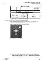
Страница 24: ...manuals in case an electrionic control device is installed 1 3 5 2 PRESSURE SETTINGS Pressure safety limit switches Suction pressure 1 Setting 5oC below design evaporating temp Min 0 3 bar a Suction and intermediate pressure Setting Max refer to Product Information PI Discharge pressure Page 24 Setting 5oC above design condensing temp Max 26 bar a Grasso V 300 T Grasso V 450 T Grasso V 600 T 1 Set...

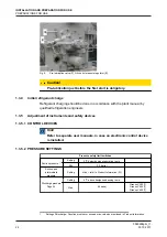
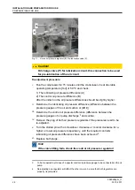
Страница 25: ...SURE REGULATORS It is possible that after the compressor has been installed the lubrication oil pressure regulator needs to be adjusted Location pressure regulators control and lubricaton Fig 10 Oil lubrication pressure regulator A 2 The oil pressure regulator is adjusted at the works but it may occur that this setting should be corrected during the initial run and also if the value 1 5 or 2 5 bar...

Страница 26: ... iii Determine the control oil pressure difference difference between the pressure gauges of oil pump discharge 3 and suction iv Remove the plug of both oil pressure regulators if the pressures need to be re adjusted v Turn the slotted pin with a screwdriver clockwise or counter clockwise for a higher or lower oil pressure respectively until the required control lubricating oil pressure difference...

Страница 27: ...be put in or out of action either individually or collectively by means of solenoid valves Warning Due to start up limitations and to limitations of part load operation it may be that not all available part load steps are allowed under certain conditions Use of incorrect control steps can damage compressor and or components For a detailed description about start up and part load limitations refer ...

Страница 28: ...sight glass vi Stop valves to the pressure gauges are open vii Suction stop valve is closed in case the evaporating temperature is much higher than the design evaporating temperature and the discharge stop valve is open and in case of two stage compressors that the stop valves in the intermediate circuit lines are open viii Stop valve in the oil return line of the oil separator if present is close...

Страница 29: ...rom the oil separator if present 9 After 50 hours of operation retighten the coupling bolts or check and or correct the tension of the V belts and retighten the foundation bolts with due respect to the torque settings given by the supplier of the fasteners 1 3 10 2 Restart Hint For the time interval between stopping and starting refer to Main setup data overview Proceed to the complete starting pr...

Страница 30: ...nsult your supplier It is recommended to proceed with the initial start up procedure 1 3 10 5 Stopping the compressor The compressor can be stopped at any moment however consult the supplier if further actions are required INSTALLATION AND PREPARATION FOR USE 0089288gbr_11 30 30 10 2017 ...

Страница 31: ... of installation operating conditions and local regulations In the case of automatically controlled plants the periodical inspection are particularly important The table below sums up all the points on the compressor that have to be inspected or maintained along with inspection and maintenance frequencies 2 2 Survey of periodical inspections Apart from the check points in the table below the sound...

Страница 32: ... temperature min During compressor standstill the lower part of the crankcase must remain warmer than the surroundings 20 C NH3 Condition of V belts Check belts for 1 Wear fraying cuts etc and ensure that they do not touch the groove bottom 2 Tension Too low a tension gives rise to excessive flapping or oscillation in operation For correct tension consult Grasso instruction 0087516 Adjustment and ...

Страница 33: ...l Warning It is expressly pointed out that it is not permitted to mix different types of oil If another type of oil is used first remove all the stale oil in the filters oil pump crankcase shaft seal oil separator and oil drains of the installation 2 4 1 Topping up oil with compressor operating Hint Use Grasso s hand operated oil pump part no 18 13 121 Topping up oil is permitted during compressor...

Страница 34: ...as been completed the compressor package must be evacuated and undergo a vacuum test Evacuation is used to remove air and moisture from the compressor package 2 5 4 START UP AFTER SERVICING 1 STATUS Compressor package is dried and still evacuated 2 Charge the oil separator if present with oil See the appropriate Product Information for the correct quantity 3 Charge the compressor crankcase with oi...

Страница 35: ...ERS General The frequency of exchanging oil discharge filter oil suction filter and compressor suction gas filter s depends on the condition of the refrigeration system Besides the maintenance schedules it is recommended to exchange all filters when the compressor is overhauled and also in case the refrigeration plant has been modified Hint An oil discharge oil running in filter is factory mounted...

Страница 36: ... original valves can be inspected and repaired or replaced if necessary later 2 9 COMPRESSOR PURGING Procedure to purge the compressor after maintenance jobs STATUS Stop valves of suction discharge and oil return line are still closed refer to Section 2 5 Page 33 and compressor is filled with oil refer to Section 2 6 Page 35 i Connect a vacuum pump to the evacuation purging valve s and evacuate as...

Страница 37: ... be helpful to quickly trace and remedy failures that interfere with the proper operation of the compressor It is emphatically pointed out that the cause of a failure must often be sought in the refrigeration installation itself Therefore it is necessary besides this table also to consult the plant manual INSPECTION AND TROUBLE SHOOTING TROUBLESHOOTING TABLE GRASSO RECIPROCATING COMPRESSORS 008928...

Страница 38: ...alve rings 5 One or more discharge valves defective Repair or renew 6 Pressure relief valve is leaking Repair or renew D Suction pressure too low 1 Suction stop valve not fully open Open fully 2 Suction gas strainer blocked Renew 3 Injection control not adjusted correctly Re adjust control 4 Too little refrigerant in installation Top up with refrigerant 5 Suction pressure gauge defective Renew E C...

Страница 39: ...at working temperature 1 Lubricating oil pressure regulator not adjusted properly or defective Re adjust or renew 2 Defective oil pressure and or suction pressure gauge if present Repair or replace J Too low lubricating oil pressure 1 Too little oil in crankcase Top up oil 2 Disturbed oil circuit Oil suction and or discharge filter is dirty Renew the element of oil suction filter and or oil discha...

Страница 40: ...ce the seal vi 1 Retighten the coupling mounting bolts with the torque settings as given by the coupling manufacturer 2 Verify and if necessary correct the tension of the V belts as given in the Grasso instruction 0087516 vii Verify and if necessary correct the torque settings of all foundation bolts as given in Compressor Service Instruction Manual 3 3 First maintenance Hint For complete conditio...

Страница 41: ...ng on the operating conditions of the compressor speed evaporating temperature condensing temperature refrigerant start frequency capacity control steps etc This means that the service intervals could be significantly different The running hours mentioned in the tables are based on a single stage compressor running at 10oC 35oC NH3 at nominal speed In this case the SMS factor 1 in all other cases ...

Страница 42: ...ge maintenance Maintenance C Description maintenance A 1 Replace clean oil discharge filter clean oil suction filter 2 Visual inspection of cylinders and crankcase 3 Visual inspection of cylinder no 1 4 Check compressor running conditions 5 Check test safety equipment Description maintenance B 1 Maintenance A 2 Replace suction and discharge valve rings and springs top end overhaul 3 Inspection of ...

Страница 43: ...essary to renew the oil and or filters If there is no oil analysis available we advise to renew the oil By regularly carrying out oil analyses and registering them in a log aberrations will be noticed in an early stage which may prevent or reduce resultant damage s Note 1 When renewing the oil in the crankcase the oil in the oil separator and the oil return or oil rectifier system if fitted has to...

Страница 44: ...ual inspection Oil pump element oil control and lubrication pressure regulator Check Check Check Lubrication and control system Check Clean Clean Oil separator test oil return system Clean Clean Clean Oil cooler fan heat exchanger Visual inspection Replace Piston Rings Visual inspection Measure Gudgeon pin Visual inspection TEST Visual inspection TEST Relief valve s Check Check Check Shaft seal Oi...

Страница 45: ...tem 9 Oil return protection and oil return system 10 Electric motor and thermistors Consult motor manufacturer 11 Base frame vibration dampers and bolts 12 Piping 13 Interstage cooler interstage injection 15 Oil cooler oil side and air side and fan 16 Thermo Master MAINTENANCE Description Maintenance ABC when GMM is applied 0089288gbr_11 30 10 2017 45 ...

Страница 46: ... Oil refreshment If hygroscopical oil is used replace this always after each opening of compressor or installation 5 Oil pump IC CL IC CL IC CL IC CL IC CL IC CL Housing and element 6 IC CL IC CL IC CL IC CL IC CL IC CL Control and lubrication oil pressure regulator 7a Crankshaft IC M E IC M E Main and intermediate bearing bushes 10 Check after every maintenance job the settings and working of all...

Страница 47: ...IC M E IC M E Gudgeon pin 14 Thrust bearing IV M E IV M E IV M E IV M E IV M E IV M E Running surfaces Axial play 15 Capacity control IC IV IC IV IC IV IC IV IC IV IC IV IC IV IC IV Solenoid valves and coils 16 RE RE IV IV RE RE Seals of cap control piston 17 IC IC IC IC IC IC Cap Control mechanism 18 Compressor housing IC IV IC IV IC IV IC IV IC IV IC IV IC IV IC IV Crankcase heater 19 CL CL CL C...

Страница 48: ...IC IC IC IC IC IC IC IC Alignment 29 IC IC IC IC IC IC IC IC V belts 30 Electric motor Refer to specifications of motor manufacturer 31 Optionals IC IC IC IC IC IC CL IC CL IC Oil level switch 32 IC IC IC IC IC IC IC IC Safety switches 33 IC IC IC IC IC IC IC IC Gauges 34 IC IC IC IC IC IC IC IC Thermostats 35 IC IC IC IC IC IC IC IC Thermometers 36 IC IC IC IC IC IC IC IC Electrical control syste...

Страница 49: ...e 44 RE RE RE RE RE RE RE Oil cooler oil side refrigeration oil 45 Refer to specifications of motor manufacturer Oil cooler electic motor fan 46 ME ME C L ME C L ME C L ME C L ME C L ME C L ME C L Cylinder head water cooling system 10 Check after every maintenance job the settings and working of all safety devices regulators and the running conditions according to the Service Instruction Manual SI...

Страница 50: ...he maintenance to the actual running conditions In other words On time maintenance This results in nearly all cases in longer service intervals and significantly less maintenance costs For industrial refrigeration compressors this is a unique development To maintain the highest level of reliability even with extended service intervals this series is fitted with the best possible components availab...

Страница 51: ...uction superheat delta t Grasso V min 0 C Superheat LP suction Grasso VT Actual suction temperature ta Grasso V T min 50 C Discharge pressure condensing pressure tc saturated condensing temperature 14 15 Ps 16 tc Grasso V 300 T 600 T max 26 0 bar a 60 C Discharge pressure condensing pressure 17 18 Grasso V 700 T 1800 T 24 0 bar a 56 C 13 In practice it is not so much the individual operation limit...

Страница 52: ...ure in crankcase toil C min 10oC and Tsaturated crankcase pressure at stand still 15 K Indicated minimum value is the lowest oil temperature at which the compressor is allowed to be started max 70 oC depending on type of oil The maximum oil temperature depends on the operating conditions of the compressor and the oil type used A minimum actual oil viscosity of 10 cSt in the bearings is always requ...

Страница 53: ...iod of compressor standstill or when the compressor operates on a batch type freezing tunnel just loaded with warm products Under these circumstances it is not permitted to switch over to two stage operation with minimum capacity until the H P cylinders already in operation have lowered in single stage the evaporating temperature so that the corresponding working point at the condensing temperatur...

Страница 54: ... Solenoid UNL NO No 1 NC No 2 NC No 3 NC No 4 NC Cylinder number solenoid valves 300 700 1 2 3 4 450 1100 3 4 2 5 6 1 600 1400 5 6 7 8 2 4 1 3 1800 Before Sept 2014 7 8 5 6 9 10 1 2 3 4 1800 From Sept 2014 5 7 8 9 10 1 2 3 4 6 Capacity control steps Compressor type Capacity 20 Cylinders Solenoids V 300 V 700 25 1 50 1 2 1 75 1 2 3 1 2 100 1 2 3 4 1 2 3 V 450 V 1100 33 3 4 50 3 4 2 1 67 3 4 5 6 2 8...

Страница 55: ...5 7 8 9 10 6 1 4 70 5 7 8 9 10 1 2 1 2 80 5 7 8 6 3 4 1 2 2 3 4 90 5 7 8 3 4 9 10 1 2 1 2 3 100 5 7 8 3 4 9 10 1 2 6 1 2 3 4 4 5 DIAGRAMS TWO STAGE Solenoid valve cylinder numbering for electric capacity control Compressor type Solenoid UNL NO 21 No 1 NC No 2 NC No 3 NC No 4 NC Cylinder number 22 solenoid valves 300T 700T 4hp 1 2 3 450T 1100T 4hp 1 2 3 5 6hp 20 Refer to the swept volume expressed ...

Страница 56: ... Fast pull down 50 2 3 4 2 2 0 50 1 4 5 6 1 3 1 0 Starting only Fast pull down 75 1 2 3 4 1 2 3 0 75 2 3 4 5 6 2 3 1 5 Starting only Fast pull down 100 1 2 3 4 5 6 1 2 3 2 0 600T 1400T 0 6 0 0 Starting only Fast pull down 33 1 2 6 1 2 0 33 3 6 4 8 2 3 1 0 Starting only Fast pull down 50 1 2 3 6 1 2 3 0 50 1 2 6 4 8 1 3 1 5 Starting only Fast pull down 67 1 2 6 4 8 1 2 3 2 0 21 UNL Unloaded start 2...

Страница 57: ... 5 6 1 3 3 0 43 3 4 10 5 6 3 4 1 5 Starting only Fast pull down 57 1 2 6 7 8 9 1 2 2 0 71 1 2 5 6 7 8 9 1 2 3 2 5 86 1 2 3 4 10 7 8 9 6 1 2 4 2 0 100 1 2 3 4 10 5 6 7 8 9 1 2 3 4 2 3 23 Refer to the swept volume expressed as a percentage of the full load swept volume of the LP cylinders 24 Each phi has its own field of application Refer Page 56 25 For starting up procedure refer Section 4 3 Page 5...

Страница 58: ...y should always be more than 10 cSt Assumed is that the oil temperature at the bearing surfaces 15 K above crankcase oil temperature A higher ISO VG number should be chosen when refrigerant solubility in crankcase is expected Remarks 1 Using ISO VG100 oils to increase viscosity at high expected cranckcase temperatures makes no sense as the friction heat will increase that much that the oil tempera...

Страница 59: ...PT F 46 Energol LPT 68 54 68 CASTROL Icematic 299 56 CPI CP 1009 68 69 H2 EXXON MOBIL Zerice S46 Zerice S68 Arctic 300 48 68 68 47 68 FUCHS Reniso KS 46 Reniso KC 68 KROON OIL Carsinus FC 46 68 46 PETRO CANADA Reflo 68A Reflo XL 58 H2 H2 GEA PR OLEO C MH68A PR OLEO C MH68A FG 68 68 H2 H1 Klüber Summit RHT 68 68 H2 Kuwait Petroleum Q8 Stravinsky C 55 SHELL Refrigeration Oil S2 FR A 68 SUN OIL Sunis...

Страница 60: ...damage the crank shaft and cylinder liners or even more parts When pre lubrication 1 Before initial start up 2 Before start up after overhauling compressor 3 Before start up after renewal of oil 4 Before start up after standstill period of more than 1 month Pre lubrication procedure Location pre lubrication valve refer Figure 15 Page 60 Figure 16 Page 61 1 Top up crankcase to the minimum required ...

Страница 61: ...Fig 16 Grasso V 6 Pre lubrication valve APPENDIX Product Information PI 0089288gbr_11 30 10 2017 61 ...

Страница 62: ...ne of the largest providers of innovative equipment and process technology GEA Group is listed in the STOXX Europe 600 Index We live our values Excellence Passion Integrity Responsibility GEA versity GEA Refrigeration GEA Refrigeration Netherlands N V Parallelweg 25 5223 AL s Hertogenbosch Netherlands Phone 31 0 73 6203 911 info gea com gea com ...

Отзывы: