background image

November 2004

D-12

PanaView™ for IDM-Compatible Meters (916-086B)

Handling Site Files

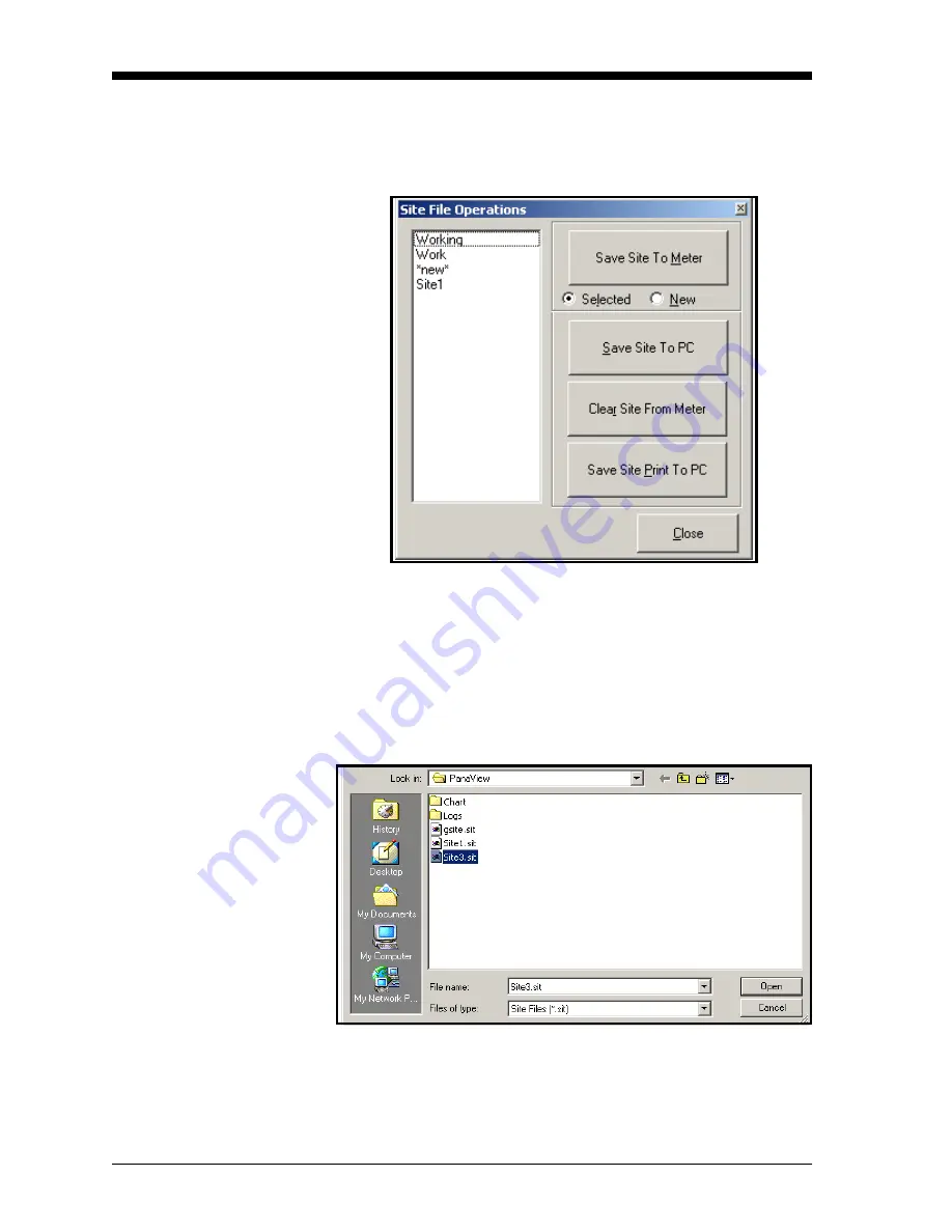
To access site files, click on the 

Site Files

 button in the 

Properties


window. The 

Site File Operations

 window (shown in Figure D-14 

below) opens.

Figure D-14:  The 

Site File Operations

 Window

Saving an Existing Site to 

the Meter

To save an existing site to the meter:

1.

Select the radio button for 

Selected

 and highlight an existing site 

in the left pane.

2.

Then click on the 

Save Site to Meter

 button.  A screen opens 

similar to Figure D-15 below. 

Figure D-15:  Site File Selection

3.

Highlight the desired site and click 

Open. PanaView

™ sends the 

site to the meter.

Содержание XGS868

Страница 1: ...GE Infrastructure Sensing Model XGS868 Steam Ultrasonic Mass Flow Transmitter 1 2 Channel Programming Manual ...

Страница 2: ...am Ultrasonic Mass Flow Transmitter 1 2 Channel Programming Manual 910 196PC November 2004 Model XGS868 is a GE Panametrics product GE Panametrics has joined other GE high technology sensing businesses under a new name GE Infrastructure Sensing ...

Страница 3: ...ties arising from course of dealing or usage or trade Return Policy If a GE Infrastructure Sensing Inc instrument malfunctions within the warranty period the following procedure must be completed 1 Notify GE Infrastructure Sensing Inc giving full details of the problem and provide the model number and serial number of the instrument If the nature of the problem indicates the need for factory servi...

Страница 4: ...1 11 Base Temperature 1 12 Pressure Input 1 12 Base Pressure 1 12 Low Pressure Switch 1 13 Quality Input 1 13 Entering Setup Data 1 15 Set Transducer Signal Settings 1 15 Setting Response Time V Averaging 1 18 Initializing Setup Parameters Default Setup 1 18 Using Advanced Features 1 19 Entering Global Data 1 21 Entering Global System Data 1 21 Setting Up Inputs and Outputs 1 24 Configuring the Co...

Страница 5: ...User Program C 7 Displaying Measurements C 9 Setting Up the Display C 10 RCCU Errors C 13 Replacing the RCCU Battery C 14 Standard Version C 14 Intrinsically Safe Version C 15 Appendix D PanaView for IDM Compatible Meters 916 086B Introduction D 1 IDM Compatible Flowmeters D 2 Wiring the RS232 Interface D 2 Starting Up D 2 Setting Up the Communications Port D 3 Adding an IDM Compatible Meter D 5 E...

Страница 6: ...Chapter 1 ...

Страница 7: ... Site Data Introduction 1 1 Programming Methods 1 2 Activating a Channel 1 3 Entering System Data for the Channel 1 4 Entering Transducer and Pipe Parameters 1 7 Entering Setup Data 1 15 Entering Global Data 1 21 ...

Страница 8: ...ent method Channelx System enter the individual channel parameters Channelx Pipe Parameters enter the pipe geometry and other parameters Channelx Input Output set up the inputs and outputs Channelx Setup set the signal limits response times and mass flow status Global System select system units English and metrics Global Input Output set up error handling option cards and display Global Comm Port ...

Страница 9: ...e XGM868 through wireless infrared transmissions Note The XGM868 cannot be programmed at the electronics enclosure One of the above methods must be used Although the actual displays differ somewhat the general procedures are the same for all three programming methods This chapter provides detailed IDM programming instructions If you are using PanaView see Appendix D PanaView for IDM Compatible Met...

Страница 10: ... for locating the acoustic signal and for high velocity measurements It is more robust in a noisy environment than the Measure technique Skan Measure is the preferred technique to use for low velocity measurements If Skan Only is selected at the above prompt the meter uses this technique exclusively However if Skan Measure is selected the meter uses Skan Only to find the acoustic signal and then t...

Страница 11: ...lecting the Volumetric Units 1 Use the pull down menu to select the desired volumetric units for the flow rate display and press Next Item Enter Available units are listed in Table 1 1 below 2 Use the pull down menu to select the desired time units for the flow rate display and press Next Item Enter 3 Use the pull down menu to select the desired number of digits to the right of the decimal point i...

Страница 12: ...ow units for the flow rate display and press Next Item Enter The available units for this prompt are determined by the selection made at System Units See Table 1 2 below 2 Use the pull down menu to select the desired time units for the mass flow rate display and press Next Item Enter 3 Use the pull down menu to select the desired number of digits to the right of the decimal point in the mass flow ...

Страница 13: ...e Channel PROGRAM window Do one of the following To continue entering quick startup data continue to Step 3 in Entering Transducer and Pipe Parameters on the next page To continue regular programming refer to Appendix A Menu Maps to navigate to the desired menu To leave the User Program press Exit Page twice ...

Страница 14: ...Proceed to Special Transducers below IMPORTANT Special transducers have no engraved number on the head and are rarely used Examine the transducer head carefully for a number Special Transducers 1 Assign a number between 91 and 99 for the special transducer and press Next Item Enter 2 Use the pull down menu to select the transducer frequency supplied by the factory and press Next Item Enter Note Th...

Страница 15: ...pe size data which can be found in Sound Speeds and Pipe Size Data manual 914 004 IMPORTANT Because the units cannot be independently chosen for this parameter the value must be entered in the same units used for the pipe OD 3 Enter the path length of the ultrasonic signal then use the pull down menu to select the units Press Next Item Enter Note If a spoolpiece was ordered with the meter the tran...

Страница 16: ...r second in the gas to be measured and press Next Item Enter 7 Enter a value for the flow calibration factor and press Next Item Enter The default value is 1 00 but values between 0 50 and 2 0 may be entered Procedure Options After entering the Calibration Factor IDM returns to the Channel PROGRAM Do one of the following To continue entering quick startup data press EXIT PAGE once and proceed to S...

Страница 17: ...EDIT MENU from the Edit Functions menu 2 Select Channelx 3 Select Input Output 4 Enter a value from 0 to 1 ft sec 0 to 0 30 m sec for the zero cutoff and press Next Item Enter The recommended setting is 0 1 ft sec 0 03 m sec Assume Saturation This prompt permits you to use a single input for either temperature or pressure to measure mass flow The User Program contains a table that correlates press...

Страница 18: ...r to set up the option card in Slot 1 that will supply the live temperature input and press Next Item Enter Note If Slot 1 contains an activated option card with an analog input assigned to Temperature or an RTD input Slot 1 appears as an option at the above prompt If the process temperature is stable a fixed value may be used but most applications require a live temperature input If there is no a...

Страница 19: ...d to Pressure Slot 1 appears as an option at the above prompt If the process pressure is stable a fixed value may be used but most applications require a live pressure input If there is no active option card for pressure the meter assumes you are using a fixed pressure 2 Proceed to one of the following sections If you selected Fixed proceed to Step 3 If you selected Slot 1 proceed to Step 4 3 Ente...

Страница 20: ... water Thus a quality value of 1 0 indicates 100 gas 1 Use the pull down menu to select a fixed steam quality value or to set up the option card in Slot 1 that will supply the live steam quality input and press Next Item Enter Note If Slot 1 contains an activated option card with an analog input that has been programmed as Special Slot 1 appears as an option at the above prompt Normally a fixed va...

Страница 21: ...e Options After completing the above steps IDM returns to the Channel PROGRAM window Do one of the following To continue programming refer to Appendix A Menu Maps for IDM to navigate to the desired menu To leave the User Program press Exit Page twice ...

Страница 22: ...the limits for the incoming signal and other parameters affecting the transducer signal For example the programmed signal strength low limit may be used to determine the trigger point for an alarm Caution The Signal default settings are suitable for most applications Consult the factory before changing any of these parameters Only after consulting the factory complete the following steps to progra...

Страница 23: ...ussion of error codes Velocity High Limit 500 to 500 ft sec 150 to 150 m sec 75 0 ft sec 23 m sec The E3 VELOCITY RANGE error messages appears when the calculated fluid velocity exceeds the programmed VELOCITY HIGH LIMIT value See Chapter 2 Error Codes in the Service Manual for a discussion of error codes Acceleration Limit 0 to 250ft s 0 to 76m s 50 ft s 15 m s The E6 CYCLE SKIP error message app...

Страница 24: ...hifts 0 to 10 3 The number of shifts corresponds to the actual number of transmits per cycle number of signals added together in one direction to produce an averaged signal for one interrogation of the fluid and need only be changed if the environment is very noisy or the acoustic signal is weak A Divisor 0 1 to 10 2 5 The Divisor used to calculate the Measure Mode integrated threshold level is no...

Страница 25: ...e Options After completing the above steps IDM returns to the Channel SET UP window Do one of the following To continue programming refer to Appendix A Menu Maps for IDM to navigate to the desired menu To leave the User Program press Exit Page three times Initializing Setup Parameters Default Setup Use this option to initialize reset all of the parameters within the Set up menu to their default va...

Страница 26: ...or table cannot be edited 1 Open the SITE EDIT MENU from the Edit Functions menu 2 Select Channelx 3 Select Set up 4 Select Advanced Features 5 Select Multiple K Factors 6 Use the pull down menu to select whether to activate or deactivate multiple K factors and press Next Item Enter Note If you select Off go to Procedure Options on the following page 7 Use the pull down menu to select whether to e...

Страница 27: ...nu However setting the Mass flow calculation prompt to Yes overrides this value and uses the density entered at the following prompt to calculate mass flow 1 Open the SITE EDIT MENU from the Edit Functions menu 2 Select Channelx 3 Select Set up 4 Select Advanced Features 5 Select Mass flow calculation 6 Use the pull down menu to select whether activate or deactivate mass flow mass flow is calculat...

Страница 28: ...1 24 Communication Port used to set up the serial communications port see page 1 36 Based on the selection made above proceed to the appropriate section of this chapter for instructions While following the programming instructions refer to Figure A 3 in Appendix A Remember to record all programmed data in Appendix B Data Records Entering Global System Data This menu enables you to select system un...

Страница 29: ...r the totalized flow rate display and press Next Item Enter Available units are listed in Table 1 5 above 2 Use the pull down menu to select the desired number of digits to the right of the decimal point in the totalized flow rate display and press Next Item Enter 3 Do one of the following If MASS FLOW is ON proceed to Selecting the Mass Flow Units below If MASS FLOW is OFF the meter returns to th...

Страница 30: ...Enter 4 Use the pull down menu to select the desired units for the totalized mass flow rate display and press Next Item Enter The available units for this prompt are determined by the selection made at System Units 5 Use the pull down menu to select the desired number of digits to the right of the decimal point in the totalized mass flow rate display and press Next Item Enter Procedure Options Aft...

Страница 31: ...ring an error condition See Chapter 2 Error Codes in the Service Manual for a discussion of the built in error codes 2 Channel meters have an additional option for error handling To access this submenu 1 Open the SITE EDIT MENU from the Edit Functions menu 2 Select Global 3 Select Input Output 4 Select Error Handling 5 Use the pull down menu to select the desired option for error handling and pres...

Страница 32: ...menu To leave the User Program press Exit Page three times Option Output Response Totalizer Response Hold Last Value Holds the last good reading Continues to totalize based on the last good flow reading Force Low Forces the outputs to the low set point Stops totalizing Force High Forces the outputs to the high set point Stops totalizing ForceHigh High Forces the outputs 10 above the high set point...

Страница 33: ...ure A 4 in Appendix A Accessing the Output 1 Open the SITE EDIT MENU from the Edit Functions menu 2 Select Global 3 Select Input Output 4 Select Options 5 Select Slot 0 or Slot 1 depending on which output you want to set up 6 Use the pull down menu to select the desired output and press Next Item Enter Note Output letters A B etc correspond to the output wiring terminal numbers from top to bottom ...

Страница 34: ...iagnostic parameters that appear at the previous prompt See Chapter 3 Diagnostics of the Service Manual for a complete description of these options Note The measurement units that appear in these prompts are those selected in the Global System window earlier in this section Procedure Options After completing the above steps IDM returns to the Input Output window Do one of the following To continue...

Страница 35: ... Use the pull down menu to select the desired input measurement and Next Item Enter Do one of the following If Off was selected go to Procedure Options below If Pressure or Temperature was selected proceed to Step 5 If Special was selected to set up the input as a live special input proceed to the next step 3 Enter a name for the input and press Next Item Enter 4 Enter a unit of measurement for th...

Страница 36: ... Input A corresponds to pins 1 2 and 3 Input B corresponds to pins 4 5 and 6 etc Setting Up the RTD Input 1 Enter a label for the RTD input and press Next Item Enter 2 Use the pull down menu to select the desired input type and Next Item Enter Do one of the following If Off was selected go to Procedure Options below If Temperature was selected proceed to the next step 3 Enter a temperature value f...

Страница 37: ...te Output letters A B etc correspond to the output wiring terminal numbers from top to bottom For example Output A corresponds to pins 1 2 and 3 Output B corresponds to pins 4 5 and 6 etc Selecting the Alarm Type 1 Use the pull down menu to select the desired alarm type and press Next Item Enter 2 Do one of the following If you selected Off IDM returns to the Input Output window go to Procedure Op...

Страница 38: ...epresents all of the individual diagnostic parameters that appear at the previous prompt See Chapter 3 Diagnostics of the Service Manual for a complete description of these options Note The measurement units that appear in these prompts are those selected in the Global System window earlier in this section 8 Enter a value for the trigger point of the alarm and press Next Item Enter Go to Procedure...

Страница 39: ...steps to set up the totalizer outputs of an option card installed in Slot 1 Accessing the Totalizer Output 1 Open the SITE EDIT MENU from the Edit Functions menu 2 Select Global 3 Select Input Output 4 Select Options 5 Select Slot 1 6 Use the pull down menu to select the desired input and press Next Item Enter 7 Do one of the following If you selected Off IDM returns to the Input Output window Go ...

Страница 40: ...frequency of the totalizer pulses and press Next Item Enter Note A complete pulse consists of equal amounts of ON and OFF times Choose a value that is compatible with the frequency counter to be used 4 Enter a value for the number of measurement units represented by each pulse and press Next Item Enter Procedure Options After completing the above steps IDM returns to the Input Output window Do one...

Страница 41: ... you selected Off IDM returns to the Input Output window Go to Procedure Options on the following page If you selected Frequency and are using a 1 Channel meter proceed to Step 2 in the next section 2 Channel meter proceed to Step 1 in the next section Note Output letters A B etc correspond to the output wiring terminal numbers from top to bottom For example Output A corresponds to pins 1 2 and 3 ...

Страница 42: ... the frequency output range and press Next Item Enter 5 Enter a value between 1 and 10 000 for the frequency at full scale and press Next Item Enter Procedure Options After completing the above steps IDM returns to the Input Output window Do one of the following To continue programming refer to Appendix A Menu Maps for IDM to navigate to the desired menu To leave the User Program press Exit Page t...

Страница 43: ...ions refer to Figure A 3 in Appendix A Setting Up the Serial Port Use the steps below to configure the communications port 1 Open the SITE EDIT MENU from the Edit Functions menu 2 Select Global 3 Select Comm Port 4 Enter a meter address between 1 and 127 and press Next Item Enter The default address is 1 A meter address is only necessary for communication with the GE Infrastructure Sensing Instrum...

Страница 44: ...ll down menu to the MODBUS stop bits and press Next Item Enter 4 Enter a MODBUS meter address between 1 and 254 and press Next Item Enter The default address is 1 IMPORTANT You must reboot the XGS868 to load the new settings Procedure Options After completing the above steps IDM returns to the Global PROGRAM window Do one of the following Refer to the following section Requesting Parameters Using ...

Страница 45: ...in Bytes 1 0 1 Clear Ch1 Totalizers 2 16 bit signed 2 2 Not Used 2 16 bit signed 3 4 Velocity 2 4 2 16 bit int 5 8 Act Volumetric Q DIGITS 4 IEEE 32 bit 7 C Std Volumetric Q DIGITS 4 IEEE 32 bit 9 10 Fwd Totals T DIGITS 4 2 16 bit int 11 14 Rev Totals T DIGITS 4 2 16 bit int 13 18 Tot Digits 0 2 14 1A Mass Flow M DIGITS 4 IEEE 32 bit 16 1E Fwd Mass Totals MT DIGITS 4 2 16 bit int 18 22 Rev Mass To...

Страница 46: ... 28 Ch1 Timer 2 4 2 16 bit int 23 2C Ch1 Error Code 0 2 24 2E Ch1 Sound Speed 3 4 2 16 bit int 26 32 Ch1 Steam Density 4 4 2 16 bit int 28 36 Ch1 Sig Strength Upstream 1 4 2 16 bit int 30 3A Ch1 Sig Strength Downstream 1 4 2 16 bit int 32 3E Ch1 Temperature 2 4 2 16 bit int 34 42 Ch1 Pressure 3 4 2 16 bit int 36 46 Ch2 Velocity 2 4 2 16 bit int 38 4A Ch2 Act Volumetric Q DIGITS 4 IEEE 32 bit 40 4E...

Страница 47: ...erature 2 4 2 16 bit int 67 84 Ch2 Pressure 3 4 2 16 bit int 69 88 Avg Velocity 2 4 2 16 bit int 71 8C Avg Act Volumetric Q DIGITS 4 IEEE 32 bit 73 90 Avg Std Volumetric Q DIGITS 4 IEEE 32 bit 75 94 Avg Fwd Totals T DIGITS 4 2 16 bit int 77 98 Avg Rev Totals T DIGITS 4 2 16 bit int 79 9C Avg Tot Digits 0 2 80 9E Avg Mass Flow M DIGITS 4 IEEE 32 bit 82 A2 Avg Fwd Mass Totals MT DIGITS 4 2 16 bit in...

Страница 48: ...Chapter 2 ...

Страница 49: ...troduction 2 1 Setting Up the LCD 2 1 Adjusting LCD Contrast and Brightness 2 3 Clearing Totals 2 3 Pausing and Restarting the Measurement 2 4 Uploading Files to the PC 2 4 Deleting Files from the XGS868 Memory 2 5 Printing Data 2 5 ...

Страница 50: ...see page 2 4 Uploading Files to the PC see page 2 4 Deleting Files from the XGS868 Memory see page 2 5 Printing Data see page 2 5 Setting Up the LCD Use the Instrument Data Manager IDM to establish communications with the XGS868 Then complete the following instructions to display the desired data on the LCD refer to Figure A 3 in Appendix A Use the following steps to set up the display 1 Open the ...

Страница 51: ... 9 until all of the specified OF LCD PARAMS have been set up After leaving the User Program the XGS868 will reset itself and will begin to display the parameters specified in this section If more than one parameter was set up each of the parameters will be displayed in sequence with a pause of several seconds between display changes Procedure Options After completing the above steps IDM returns to...

Страница 52: ...n a hazardous environment adjust the LCD brightness and contrast in a safe area before mounting the enclosure 2 With power still applied to the meter carefully use a small screwdriver to adjust the LCD brightness Turning the BKLT backlight pot fully clockwise yields maximum brightness 3 In a similar manner adjust the CONT contrast pot to set the LCD contrast as desired At either extreme of the CON...

Страница 53: ...surements and exits the Edit Functions menu Uploading Files to the PC Any files stored in the XGS868 s memory may be uploaded to the PC s disk The files may then be displayed and examined via IDM To upload a log file complete the following steps see Figure A 6 on page A 6 1 Open the FILE MENU from the Edit Functions menu 2 Select Upload File 3 Use the pull down menu to select the desired memory lo...

Страница 54: ...CCU However any of the data stored in its memory may be printed via the built in RS232 communications port using a computer terminal In order to use the capability the XGS868 must be linked to the computer terminal with the optional Instrument Data Manager IDM software Note See Chapter 1 Installation of the Startup Guide for instructions on wiring the RS232 serial port For more information on seri...

Страница 55: ...Chapter 3 ...

Страница 56: ...Logging Data Introduction 3 1 Setting Up a Standard Log 3 1 Setting Up an Error Log 3 6 Checking the XGS868 Memory 3 9 Stopping a Log 3 9 ...

Страница 57: ...tions Unit RCCU via an infrared transmission See Appendix C Remote Control Communications Unit Setting Up a Standard Log A standard log is used to record up to six flow rate measurement parameters in a log file stored in the XGS868 s memory Complete the following steps to set up a log see Figure A 5 in Appendix A 1 Open the LOG EDIT MENU from the Edit Functions menu 2 Select Create Standard Log 3 ...

Страница 58: ...nostics of the Service Manual for a complete description of these options Note The measurement units that appear in these prompts are those selected in the Global System window earlier in this section 3 Repeat Steps 1 and 2 until until all of the log channels have been set up 4 Do one of the following If you selected a totalized value proceed to the next step If you selected a non totalized value ...

Страница 59: ...defined by the DURATION time previously recorded data is overwritten by the new data IMPORTANT If there is insufficient memory available to store a specified log setup of that log will not be permitted Selecting the Start Time 1 Use the pull down menu to select the desired start time for the log and press Next Item Enter 2 If you selected OK proceed to Selecting the Start Date below EDIT proceed t...

Страница 60: ...non circular log proceed to Selecting the End Time below If you are creating a circular log proceed to Selecting the Duration on the next page Selecting the End Time 1 Use the pull down menu to select the desired start time for the log and press Next Item Enter 2 If you selected OK proceed to Selecting the End Date below EDIT proceed to the next step TIMED use the pull down menu to select how long...

Страница 61: ...ment 1 Use the pull down menu to select the desired time increment and Next Item Enter The time increment is the frequency at which the Model XGS868 takes and records data measurements If any reading takes longer than the programmed time increment the log is filled in with the next consecutive reading For example assume that a velocity value of 3 ft sec is recorded at 12 00 00 in a log with a time...

Страница 62: ...ient room for the expected size of the log file being created After the memory location for the log file has been specified IDM displays the amount of that type of memory available IMPORTANT If a circular log is being set up DO NOT choose FLASH as the memory location for the log file Note The PCMCIA option only appears if such a card has been installed 4 Enter a log name up to five characters and ...

Страница 63: ... until all of the log channels have been set up 4 Do one of the following If you selected a totalized value proceed to the next step If you selected a non totalized value for the log and selected FLASH as the log memory location proceed to Selecting the Start Time on the next page selected NVR or PCMCIA as the log memory location proceed to Step 6 5 Use the pull down menu to clear or keep current ...

Страница 64: ... Enter 2 If you selected OK proceed to Selecting the Start Date below EDIT proceed to the next step NOW press Next Item Enter to acknowledge the message You have completed creating an error log 3 Use the pull down menu to select AM or PM Then enter the desired hour 1 12 and press Next Item Enter Note If you enter a start time earlier that the current time and error will occur 4 Enter the desired m...

Страница 65: ...s that some old logs be cleared to make room for the new log Refer to Figure A 5 in Appendix A Complete the following steps to set up an error log 1 Open the LOG EDIT MENU from the Edit Functions menu 2 Select Memory 3 IDM displays the available memory Press EXIT PAGE Stopping a Log Use the Stop submenu to terminate a logging process that is currently active Refer to Figure A 5 in Appendix A Compl...

Страница 66: ...Appendix A ...

Страница 67: ...e Parameters I O Menu Map A 1 Channel SETUP Menu Map A 2 Global System I O Error Handling Display Comm Port Menu Map A 3 Global Input Output Options Menu Map A 4 Log Edit Menu A 5 File Menu Clear Totalizers Pause Measurement Menu Map A 6 ...

Страница 68: ...LB LB KLB TONNE KG MASS TOTALS English Metric TONS MMLB 0 1 3 2 MASS DECIMAL DIGITS for 2 Channel meter only Channel 1 Channel 2 Skan Only Skan Measure Skan Measure Mode Channel status Burst Off Burst Site status 1 Channel 2 Channel MMACF SCF KSCF MMSCF ACF KACF VOLUMETRIC UNITS ENGLISH METRIC MMACM SCM KSCM MMSCM ACM KACM MIN SEC DAY HR VOLUMETRIC TIME MMACF SCF KSCF MMSCF ACF KACF ENGLISH METRIC...

Страница 69: ...Figure A 1 See Figure A 1 See Figure A 3 30 RESPONSE TIME M S SWITCH 60 STATS 4 2 16 8 32 XMIT SAMPLE SIZE SIGNAL LOW LIMIT VELOCITY LOW LIMIT SOUNDSPEED LIMIT AMP DISCRIM LOW AMP DISCRIM HIGH VELOCITY HIGH LIMIT DELTA T OFFSET Press YES to Default NO YES No Yes Fluid Density Off On Edit table NO YES Enter of K Factors Velocity K Factor Repeat for the of K Factors entered previously 0 2 1 4 10 Mas...

Страница 70: ...LISH METRIC BARa Kpaa Kpag BARg TOTALIZER UNITS 1 0 3 2 VOL DECIMAL DIGITS 1 0 3 2 TOTAL DECIMAL DIGITS TOTALIZER UNITS 1 0 3 2 VOL DECIMAL DIGITS 1 0 3 2 TOTAL DECIMAL DIGITS MMACF SCF KSCF MMSCF ACF KACF VOLUMETRIC UNITS ENGLISH METRIC MMACM SCM KSCM MMSCM ACM KACM MIN SEC DAY HR VOLUMETRIC TIME MMACF SCF KSCF MMSCF ACF KACF ENGLISH METRIC MMACM SCM KSCM MMSCM ACM KACM LB KLB TONNE KG MASS FLOW ...

Страница 71: ...C LABEL INPUT NAME INPUT UNITS ZERO Value FULL Scale Value Input measurement RTD Inputs OFF LABEL TEMP FULL Scale Value ZERO Value OFF FLOW ALL OTHER YES NO Failsafe OFF FREQ Slot 1 Outputs BASE FULL FULL SCALE FREQUENCY MASS MASS Measurement Name MINIMUM ON PULSE TIME UNITS PULSE Trigger point TOTL TOTL CH1 SUM Channel CH2 DIF AVE CH2 CH1 Channel SUM AVE DIF CH2 CH1 SUM Channel DIF AVE HIGH LOW F...

Страница 72: ...Y STARTTIME START DATE TODAY DEC YEAR JAN DAY MONTH PM AM END DATE EDIT OK MINUTES SECONDS END TIME EDIT OK HOUR TIMED HOURS DAYS DURATION non circular log circular log 10min 24 HR LOG TIME 7 choices 12 choices 12 choices TIME INCREMENT 5sec 9 choices 60min for STANDARD log DIF Channel 1 CH1 SUM CH2 AVE NO YES NO Is LOG circular YES totalized value non totalized value Set LOG Totals to 0 LOG LOCAT...

Страница 73: ...Connect to a New Instrument Select an Existing Instrument Scan Network for Instruments Preferences Dial Modem Hang Up Modem Exit CLEARING TOTALIZERS only if data logging option card installed SITE EDIT MENU CALIBRATION TEST PAUSE MEASUREMENT LOG EDIT MENU FILE MENU FILE LOCATION FILE LOCATION FILE LOCATION PCMCIA NVR FLASH DIRECTORY ENTER FILENAME only appears if PCMCIA card installed Upload File ...

Страница 74: ...Appendix B ...

Страница 75: ...Data Records Available Option Cards B 1 Option Cards Installed B 2 Setup Data B 3 ...

Страница 76: ...TI 2 Current Inputs 2 Totalizer Outputs 1223 05 TR 2 RTD Inputs 2 Totalizer Outputs 1223 06 FI 2 Current Inputs 2 Frequency Outputs 1223 07 FR 2 RTD Inputs 2 Frequency Outputs 1223 08 AI 2 Current Inputs 2 Standard Alarms 1223 09 HI 2 Current Inputs 2 Hermetic Alarms 1223 10 AR 2 RTD Inputs 2 Standard Alarms 1223 11 HR 2 RTD Inputs 2 Hermetic Alarms 1225 13 CO 2 Current Outputs 1225 14 CF 2 Curren...

Страница 77: ...d is installed or changed in the Model XGS868 flow transmitter record the type of card and any additional setup information in the appropriate row of Table B 2 below Table B 2 Option Cards Installed Slot Type of Option Card Additional Setup Information 0 Analog Outputs A B 1 2 ...

Страница 78: ...ec Digits Totalizer Units Global Input Output Error Handling Error Handling 2 Path Error No Yes Global Communications Port Meter Address MOD Parity Baud Rate MOD Stop Bits MOD Baud Rate MOD Address Channel Status Channel 1 Channel 2 Channel Status Off Burst Channel Status Off Burst Measure Mode Skan S M Measure Mode Skan S M Channel System Channel Label Channel Label Site Channel Msg Channel Messa...

Страница 79: ...ration Factor Channel Input Output Zero Cutoff Zero Cutoff Assume Sat No Yes Assume Sat No Yes Steam Input Type Temp Pressure Steam Input Type Temp Pressure Temp Input Temp Input Base Temp Base Temp Pressure Input Pressure Input Base Pressure Base Pressure Low Press Switch No Yes Low Press Switch No Yes Pressure Limit Pressure Limit Quality Input Quality Input Channel SETUP V Averaging Response Ti...

Страница 80: ...s B 5 November 2004 Channel SETUP Advanced Features Multi K Factors cont K Factor Velocity K Factor K Factor Velocity K Factor 11 11 12 12 13 13 14 14 15 15 16 16 17 17 18 18 19 19 20 20 Table B 3 Setup Data cont ...

Страница 81: ...Appendix C ...

Страница 82: ...Remote Control Communications Unit Using the RCCU C 1 The User Program C 6 Displaying Measurements C 9 Replacing the RCCU Battery C 14 ...

Страница 83: ...S868 s infrared receiver should have a clear line of sight to the RCCU be located within 8 ft 2 5 m of the RCCU have an angle of incidence of no more than 15 Figure C 1 RCCU Components 7 ABC 8 DEF 9 GHI OFF 6 5 4 PQR MNO JKL SEND YZ 3 VWX STU 1 2 RCV 0 PRINT MENU F2 F3 F1 PROG LOG DATA ONLINE PROGRAM On Line Operations Edit Site S L Right Arrow Key Enter Key Exit Key Left Arrow Key Shift Indicator...

Страница 84: ... functions assigned to most of the keys The complete keypad is illustrated in Figure C 2 below and a detailed description of both the unshifted and shifted functions for each of the 24 keys is listed in Table C 4 on the next page Figure C 2 The RCCU Keypad 7 ABC 8 DEF 9 GHI OFF 6 5 4 PQR MNO JKL SEND YZ 3 VWX STU 1 2 RCV 0 PRINT MENU F2 F3 F1 GE PANAMETRICS PROG LOG DATA ONLINE PROGRAM On Line Ope...

Страница 85: ...nu options when entering text deletes rest of entry and moves cursor one space to the right None Up Arrow Key in programming mode press to return to the previous prompt SEND not yet available Down Arrow Key in programming mode press to move to the next prompt RCV not yet available Zero Key use to enter a number 0 None One Key press to enter a number 1 Press 1 time to enter the letter S Press 2 tim...

Страница 86: ...to enter the letter F Nine Key press to enter a number 9 Press 1 time to enter the letter G Press 2 times to enter the letter H Press 3 times to enter the letter I Clear Key press to enter the CLEAR menu See Chapter 5 Clearing Data for details None Exit Key press to leave the current menu saving entered values and return to the next higher menu PRNT not yet available Enter Key press to accept the ...

Страница 87: ...of sight to the RCCU and should be located within 8 ft 2 5 m of the RCCU with an angle of incidence of no more than 15 Immediately upon activation the RCCU will perform its normal startup routine This results in a display of the GE Panametrics logo followed by these informational displays The RCCU is now ready for operation GE Panametrics Inc RCCU Remote Control Communications Unit Software Revisi...

Страница 88: ...ate through the PROG menu of the User Program The menu map may be followed in sequence or the and keys may be used to scroll through the prompt screens The key may be used to delete the last alphanumeric character that was entered from the keypad Note Be sure to record all the programming data entered in this chapter in Appendix B Data Records Programming of the CHx ACTIV CHx SYSTM CHx PIPE and GL...

Страница 89: ...iving power while the red light should glow for more than two seconds whenever a signal from the RCCU is initiated If the red light blinks repeatedly the XGS868 is not receiving the RCCU signal correctly The Send Receive lights on the RCCU blink once to indicate the sending receiving of a signal IMPORTANT Always keep the RCCU pointed directly at the XGS868 while communicating with the meter IDM ME...

Страница 90: ...d abort the opera tion Target System Info Press RCV Key RCV CANCEL F1 F2 F3 Communicating This display shows the status of the communication attempt PRESS EXIT to ESCAPE 50 Percent Complete F1 F2 F3 When the connection is estab lished this message appears briefly and is then replaced by the following display TARGET METER ID THIS IS AN XGS F1 F2 F3 ONLINE PROGRAM GGG The XGS868 is now ready to be p...

Страница 91: ...ameter Option Choices Flow Rate Value The example in Figure C 4 above is typical but the first three items in the list above may be reprogrammed to display those parameters that are most frequently used See the following section for general instructions on changing these parameters Note Error code messages may appear in the upper right corner of the LCD display For information about these error co...

Страница 92: ...lect DATA On Line Operations previous selection appears here PROG LOG DATA ONLINE PROGRAM GGG These additional options are accessed by pressing the and or keys On Line Operations previous selection appears here SITE CLEAR TEST F1 F2 F3 ONLINE PROGRAM GGG Use the and keys to find the desired time between data updates and press the Fx key under it to select that interval Live Data Update current set...

Страница 93: ... and press the Fx key under it to select it CHAN NAMES current selection appears here CH1 CH2 SUM GGG These additional options are accessed by pressing the and or keys CHAN NAMES current selection appears here DIF AVE F1 F2 F3 Table C 5 Channel Display Options Display Type Description F1 CH1 Channel 1 F2 CH2 Channel 2 F3 SUM Channel 1 Channel 2 F1 DIF Channel 1 Channel 2 F2 AVE Channel 1 Channel 2...

Страница 94: ... parame ter and press the Fx key to select it CH1 Mass flow 4500 LB HR VEL VOLUM TOTL LIVE FLOW Link GGG These additional options are accessed by pressing the and or keys CH1 Mass flow 4500 LB HR TOTL TIMER MDOT LIVE FLOW Link GGG These additional options are accessed by pressing the and or keys CH1 Mass flow 4500 LB HR MASS MASS DIAG F1 F2 F3 Table C 6 Display Parameter Options Available Choice D...

Страница 95: ...868 ce1 No Link Indicates The RCCU has received no communication from the XGS868 ce2 No Packet Rcvd Indicates The RCCU received a signal from the XGS868 but the information was not recognizable ce3 CRC Error Indicates Cyclical Redundancy Check The RCCU received a signal from the XGS868 but the command was not recognizable ce4 NAK Error Indicates Not Acknowledged error The communications link works...

Страница 96: ...ies A depleted battery must be replaced with a new one Standard Version 1 Loosen the two 2 screws along the bottom edge of the back of the RCCU housing as illustrated in Figure C 5 below Remove the battery compartment cover 2 Remove the battery connector from the top of the old battery 3 Install the battery connector on the top of the new battery 4 Replace the battery and the battery compartment c...

Страница 97: ...ry compartment cover 2 Unfasten the Velcro strap that secures the battery to the cover and remove the battery connector from the top of the old battery See Figure C 6 below Dispose of the old battery properly 3 Install the battery connector on the top of the new battery and secure the new battery to the cover with the Velcro strap 4 Replace the battery compartment cover and tighten the two 2 screw...

Страница 98: ...F F2 1 0 F1 F2 3 2 F3 F1 0 1 F1 F2 3 2 F3 F1 VOLUMETRIC UNITS VOL DECIMAL DIGITS TOTALIZER UNITS TOTAL DECIMAL DIGITS MIN SEC F1 F2 DAY HR F3 F1 VOLUMETRIC TIME Site status 1 Channel 2 Channel SYSTM RCCU Program SYSTEM F1 OFFLNE F2 ONLINE F3 PROG F1 SITE EDIT MENU PROG CHOICES CLEAR DATA F3 LOG F2 SITE F1 F2 TEST F3 only if data logging option card installed PROG F1 F3 PAUSE CAL F2 LOG F1 FILE F2 ...

Страница 99: ...PLE SIZE ZERO CUTOFF PROGRAM GLOBL CH2 CH1 Channel PROGRAM F1 F2 F3 for 2 Channel meter only RCCU Program SYSTEM F1 OFFLNE F2 ONLINE F3 PROG F1 SITE EDIT MENU PROG CHOICES CLEAR DATA F3 LOG F2 SITE F1 F2 TEST F3 only if data logging option card installed PROG F1 F3 PAUSE CAL F2 LOG F1 FILE F2 YES FLUID DENSITY Multi K factors OFF F1 NO F1 Edit table F2 ON Static Density NO F1 YES F2 of K factors K...

Страница 100: ...Name VOLUM VEL F1 CH1 F1 ZERO FULL TOTL F2 F3 Channel F2 F3 SUM F1 TOTL F1 DIF F3 F2 DIAG MASS F1 MASS F2 F3 TIME F2 all diagnostic parameters appear here only appears for 2 Channel meter Global PROGRAM Figures C 1 and C 2 SYSTM SYSTEM UNITS METER MESSAGE English Metric 1 CHANNEL UNITS 2 CHANNEL UNITS PSIg PSIa PRESSURE UNITS ENGLISH METRIC BARa Kpaa Kpag BARg TOTALIZER UNITS 1 0 3 2 VOL DECIMAL D...

Страница 101: ...hannel F3 F1 DIF AVE F2 HIGH LOW FAULT F2 F1 NO YES 2PATH ERROR HANDLING F3 F1 F2 OPTN CH1 I O F1 SYSTM F1 ERROR Global PROGRAM F2 F2 F3 LCD Global I O Channel PROGRAM CH2 F1 F2 GLOBL F3 COMM F3 for 2 Channel meter only RCCU Program SYSTEM F1 OFFLNE F2 ONLINE F3 PROG F1 SITE EDIT MENU PROG CHOICES CLEAR DATA F3 LOG F2 SITE F1 F2 TEST F3 only if data logging option card installed PROG F1 F3 PAUSE C...

Страница 102: ...ATE EDIT OK F1 F2 F3 MINUTES SECONDS END TIME EDIT OK F1 F1 F2 HOUR TIMED F2 F3 HOURS F1 DAYS DURATION F2 non circular log circular log F1 F1 10min 24 HR LOG TIME 7 choices 12 choices 12 choices TIME INCREMENT 5sec 9 choices F1 60min F3 totalized value non totalized value Set LOG Totals to 0 for STANDARD log MASS MASS DIAG F3 DIF Channel 1 CH1 F1 SUM CH2 F2 F3 F1 F2 AVE F3 F1 F2 LOG LOCATION PCMCI...

Страница 103: ...ME Another selction MORE F1 F1 NO EXIT F2 F2 YES SITE LOG F1 LOG4 YES EXIT Another selction All Sites Cleared SITE3 NAME CLEAR NAME NO if more sites available MORE F1 SITE1 F1 F1 F2 SITE2 LOG1 if more logs available F2 F2 SITE4 F3 F1 YES NO All Logs Cleared Another selction MORE F1 EXIT F2 NAME CLEAR NAME F1 LOG2 F1 F2 F2 LOG3 F3 F1 CLEAR F2 DIF F1 AVE F2 All Totals Cleared if more totals availabl...

Страница 104: ...Appendix D ...

Страница 105: ... 916 086B Introduction D 1 IDM Compatible Flowmeters D 2 Wiring the RS232 Interface D 2 Starting Up D 2 Setting Up the Communications Port D 3 Adding an IDM Compatible Meter D 5 Editing Meter Properties D 7 Changing Meter Settings D 15 ...

Страница 106: ...w you can load and save site file data create and save graph and log files display text output and graphs of live measurement data create custom templates for displaying text graph and log data interface with multiple GE Infrastructure Sensing instruments This document focuses on particular applications suitable for flowmeters that use the GE Infrastructure Sensing PanaView protocol For general Pa...

Страница 107: ...erface to communicate with a PC For details on wiring your RS232 interface please refer to the Installation chapter of your instrument s User s Manual and to the document EIA RS Serial Communications 916 054 Starting Up When the above connections have been made power up the meter and the PC then start up PanaView If a message appears as in Figure D 1 below PanaView is not able to communicate with ...

Страница 108: ...th an IDM compatible flowmeter 1 Open the New Meter Browser window and expand the network tree Then highlight the My Computer Name branch by clicking on it 2 Pull down the Edit menu by clicking on it in the menu bar 3 Click on the New menu option to select it and a submenu opens with two choices on it see Figure D 2 below Figure D 2 The Edit Menu ...

Страница 109: ...he Protocol menu the first of the drop down menus and click on IDM 6 Select any suitable available baud rate A baud rate of 19 200 is appropriate for almost all applications However if you experience periodic communication reliability problems you may wish to consider lowering the baud rate on your instrument and in PanaView IMPORTANT Be sure all the communications port settings match those made i...

Страница 110: ...the Edit menu on the menu bar if the communication port is not highlighted first the New Meter option is not active in the Edit menu 2 Click on the New option in the Edit menu see Figure D 4 below Figure D 4 New Option in the Edit Menu 3 After clicking on the New option the Meter menu option appears Click on this option to select it 4 The New IDM Meter screen shown in Figure D 5 below opens Enter ...

Страница 111: ...ul the Meter Browser shows a listing similar to Figure D 6 below Figure D 6 The Updated Network Tree However if the settings do not match or there is some other difficulty a screen appears similar to Figure D 7 below Figure D 7 Communication Error Screen The screen offers the options of trying again or of canceling the operation Click on the desired choice and then on OK to confirm the choice or o...

Страница 112: ...e it with the PC clock Read plot and save transducer signals Clear totalizers Save site files to the meter or PC Clear sites from the meter Print site files to the PC To edit the properties of your IDM compatible meter 1 Highlight the meter as shown in Figure D 6 on page D 6 2 Open the Edit menu and select the Properties option as shown in Figure D 8 below Figure D 8 The Properties Option in the E...

Страница 113: ...ollowing pages Setting the Meter Clock page D 9 Reading Transducer Signals page D 10 Plotting Transducer Signals page D 11 Saving Transducer Signals page D 11 Clearing Totalizers page D 11 Handling Site Files page D 12 Figure D 9 Properties Window for IDM Based Meter Note For illustration purposes the meter shown here is a one channel GN868 flowmeter Specific parameters will vary with your particu...

Страница 114: ... enter the time and date in the text box or click on the Sync to PC option button to have PanaView set the time and date to the current PC setting or click on the Set option button to open the dialog box shown in Figure D 10 below Set the desired date and time as indicated and click on the OK option button Figure D 10 Time and Date Selection Window ...

Страница 115: ...er is a multi channel instrument open the Channel drop down menu and click on the desired channel After a moment the Properties window appears similar to Figure D 11 below Figure D 11 Active Signal Options in Properties Window 2 To select a different signal type open the signal menu at the right shown here with Raw Upstream highlighted and click on the desired signal ...

Страница 116: ...low Figure D 12 Signal Graph Window Saving Transducer Signals To save the raw signal click Save A window opens similar to Figure D 13 below Enter the desired name and click Save to save the signal as a text file Figure D 13 Save As Window Clearing Totalizers To clear the meter totalizers click on the Clear Totalizers button in the Properties window The meter totalizers are reset to 0 ...

Страница 117: ...ow opens Figure D 14 The Site File Operations Window Saving an Existing Site to the Meter To save an existing site to the meter 1 Select the radio button for Selected and highlight an existing site in the left pane 2 Then click on the Save Site to Meter button A screen opens similar to Figure D 15 below Figure D 15 Site File Selection 3 Highlight the desired site and click Open PanaView sends the ...

Страница 118: ... site with the desired settings and click Open PanaView saves the site in the meter with the new name and the desired settings Saving a Site to the PC To save a site to the PC 1 Highlight the desired site in the left pane See Figure D 14 on page D 12 2 Click Save Site to PC A window opens similar to Figure D 13 on page D 11 3 Enter the desired site name and click Save PanaView saves the site in th...

Страница 119: ... the data from a site file as a text file for display or printout 1 Highlight the site in the left pane see Figure D 14 on page D 12 2 Click Save Site Print to PC 3 The Site File Selection window opens Figure D 15 on page D 12 Enter the desired site name now with a prt suffix and click Save PanaView displays a text version of the site as shown in Figure D 17 below Figure D 17 Printout of Site File...

Страница 120: ...n Program and change a meter s operating parameters Set up start and stop logs Calibrate and test inputs and outputs Clear various files To access meter programming 1 Enter the New Meter Browser option from the File menu 2 Expand the network tree until you reach the desired meter 3 Then expand the meter tree as shown in Figure D 18 below Figure D 18 New Meter Browser with Meter Branch ...

Страница 121: ...or a one channel GN868 flowmeter Figure D 19 Meter Tree with Edit Functions Option 5 To open a particular menu double click on that menu on the tree For example if you double click on the Site Edit Menu a window opens similar to Figure D 20 below Figure D 20 The Site Edit Menu Window Note The options listed in the left pane correspond to the options available in the GN868 PROGRAM menu For more inf...

Страница 122: ...numeric value change the value displayed in the right pane Figure D 21 The Pipe Parameters Option in the Site Edit Menu c Do one of the following Click on Next Item to proceed to the next menu item or Click on Previous Item to return back through the menu to a previous item Note If you click on either Next Item or Previous Item without changing the settings the current settings remain unchanged As...

Страница 123: ...7 When you have completed entering parameters in a given option click Exit Page to close the option You can then double click on another option or click Close to close the window You can double click on another menu to modify its settings or return to the New Meter Browser For additional PanaView functions refer to the PanaView User s Manual ...

Страница 124: ...g Up 1 37 Setting Up D 3 D 4 Correlation Peak Limit 1 16 D Default Setup 1 18 Delta T Offset 1 17 Diagnostics A Divisor 1 17 Acceleration Limit 1 16 Amplitude Discriminator High 1 16 Amplitude Discriminator Low 1 16 Correlation Peak Limit 1 16 Delta T Offset 1 17 M S Switch 1 17 Number of Shifts 1 17 Parameters 1 27 1 31 C 12 Percent of Peak 1 17 R Window 1 17 Signal Low Limit 1 16 Skan T Offset 1...

Страница 125: ...utput Channel Menu Map A 1 Input Output Error Handling 1 24 Input Output Menu 1 10 1 24 Assume Saturation 1 10 Base Pressure 1 12 Base Temperature 1 12 Low Pressure Switch 1 13 Pressure Input 1 12 Quality Input 1 13 Steam Input Type 1 11 Temperature 1 11 Zero Cutoff Value 1 10 K K Factors 1 19 Keypad RCCU C 2 Keys Table of Functions C 3 L LCD Adjusting Contrast and Brightness 2 3 Menu Map A 3 Sett...

Страница 126: ...sting Parameters 1 38 Setting Up 1 37 MODBUS Parameters Requesting 1 38 Multiple K Factors 1 19 O Option Card Alarms 1 30 Analog Inputs 1 28 1 29 1 30 Available Cards B 1 Setup Information Table B 2 Totalizer Frequency 1 34 Options Menu Alarm Relays 1 30 Analog Inputs 1 28 Analog Outputs 1 26 Frequency Outputs 1 34 RTD Inputs 1 29 Totalizer Outputs 1 32 OPTN Sub Menu 1 26 P PanaView Applications o...

Страница 127: ...Save to PC D 13 Skan T Offset 1 17 Slot 0 Analog Outputs 1 26 Output Meas 1 27 1 31 1 33 1 35 3 2 3 7 Slot Number 1 24 Soundspeed Limit 1 16 Special Transducers 1 7 Standard Log Setting Up 3 1 Static Density 1 20 Status Menu Map A 1 Steam Input Type 1 11 Stopping a Log 3 9 System Data Channel 1 4 Global 1 21 Mass Flow Units Channel 1 5 Mass Flow Units Global 1 23 Totalizer Units Channel 1 5 Totali...

Страница 128: ...Index 5 November 2004 Index cont V V Averaging 1 18 Velocity High Limit 1 16 Low Limit 1 16 Volumetric Units Channel 1 4 Global 1 22 Z Zero Cutoff Value 1 10 ...

Страница 129: ...l appropriate international national and local standard codes and practices and site regulations for flameproof apparatus and in accordance with the instructions contained in the manual Access to the circuitry must not be made during operation Only trained competent personnel may install operate and maintain the equipment The product has been designed so that the protection afforded will not be re...

Страница 130: ... A1 A2 1999 EN 50018 2000 EN50281 1 1 1998 II 2 GD EEx d IIC T5 ISSeP02ATEX008 ISSeP B7340 Colfontaine Belgium EN 61326 1998 Class A Annex A Continuous Unmonitored Operation EN61010 1 1993 A2 1995 Overvoltage Category II Pollution Degree 2 EN 60529 1991 A1 2000 IP66 following the provisions of the 89 336 EEC EMC Directive the 94 9 EC ATEX Directive and the 73 23 EEC Low Voltage Directive The units...

Страница 131: ...2 GD EEx d IIC T5 ISSeP02ATEX008 ISSeP B7340 Colfontaine Belgium EN 61326 1998 Class A Annex A Continuous Unmonitored Operation EN61010 1 1993 A2 1995 Overvoltage Category II Pollution Degree 2 EN 60529 1991 A1 2000 IP66 suivant les régles de la Directive de Compatibilité Electromagnétique 89 336 EEC d ATEX 94 9 EC et de la Directive Basse Tension 73 23 EEC Les matériels listés ci dessus ainsi que...

Страница 132: ...018 2000 EN50281 1 1 1998 II 2 GD EEx d IIC T5 ISSeP02ATEX008 ISSeP B7340 Colfontaine Belgium EN 61326 1998 Class A Annex A Continuous Unmonitored Operation EN61010 1 1993 A2 1995 Overvoltage Category II Pollution Degree 2 EN 60529 1991 A1 2000 IP66 gemäß den Europäischen Richtlinien Niederspannungsrichtlinie Nr 73 23 EG und EMV Richtlinie Nr 89 336 EG und ATEX Richtlinie Nr 94 9 EG Die oben aufge...

Страница 133: ...USA 1100 Technology Park Drive Billerica MA 01821 4111 Web www gesensing com Ireland Shannon Industrial Estate Shannon County Clare Ireland ...

Отзывы: