background image

Customizing Your System

4-30

Venue 50

 – 

Basic User Manual

Direction 5446729-100 English


Rev. 7

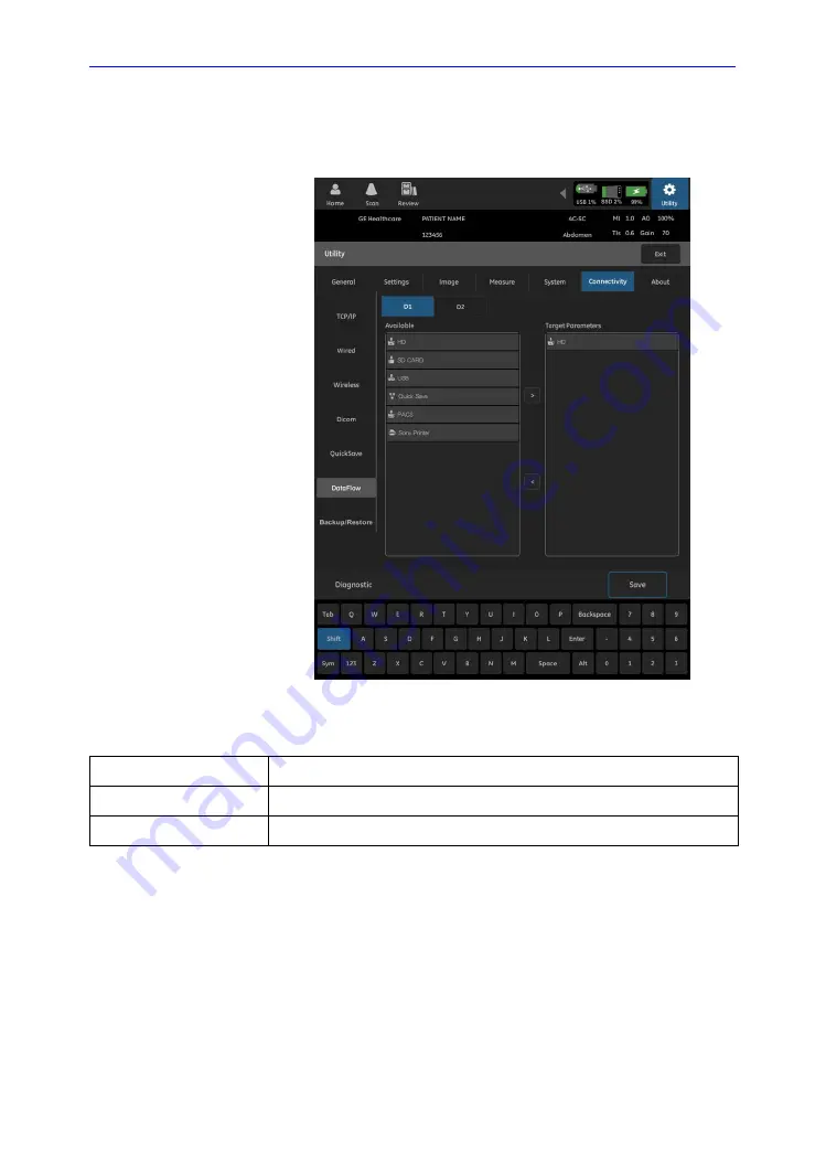
DataFlow

The 

DataFlow

 screen shows the configuration of D1 and D2:

Figure 4-19. Connectivity - DataFlow

Table 4-23:  Measure settings

D1, D2

DataFlow button to be configured.

Available parameters

The available storage media. 

Target parameters

The selected storage media.

Содержание Venue 50

Страница 1: ...Technical Publications Direction 5446729 100 English Rev 7 Venue 50 Basic User Manual R4 x x Operating Documentation Copyright 2013 2014 By General Electric Co...

Страница 2: ...al is a reference for the Venue 50 It applies to all versions of the R4 x x software for the Venue 50 ultrasound system GE P O Box 414 Milwaukee Wisconsin 53201 U S A Asia Pacific Latin America North...

Страница 3: ...Center at 1 800 682 5327 or 1 262 524 5698 REV DATE YYYY MM DD REASON FOR CHANGE Rev 1 2013 01 04 Initial Release Rev 2 2013 05 21 Update UI and software functions Rev 3 2013 09 17 Update UI and soft...

Страница 4: ...i 2 Venue 50 Basic User Manual Direction 5446729 100 English Rev 7 This page intentionally left blank...

Страница 5: ...s Group 1 Class A ISM Equipment According to IEC 60529 The footswitch rate is IP X8 MKF 2 1S 1S MED HID GP 26 Probe head immersible portion and cable are IPX7 Probe connector is not waterproof This pr...

Страница 6: ...l devices IEC 60601 2 37 Medical electrical equipment Particular requirements for the safety of ultrasonic medical diagnostic and monitoring equipment International Organization of Standards ISO ISO 1...

Страница 7: ...h Rev 7 Certifications General Electric Medical Systems is ISO 9001 and ISO 13485 certified Original Documentation The original document was written in English Country Specific Approval JAPAN MHLW Cer...

Страница 8: ...i 6 Venue 50 Basic User Manual Direction 5446729 100 English Rev 7...

Страница 9: ...vice 1 5 Owner Responsibility Owner requirements 1 6 Notice against user modification 1 7 Safety Precautions Precaution Levels 1 8 Hazard Symbols 1 9 Patient Safety 1 11 Equipment and Personnel Safety...

Страница 10: ...cting the Probe 2 39 Transporting Probes 2 40 Storing the Probe 2 40 Touch Panel Exam Function Controls 2 41 Monitor Display Monitor Display 2 42 Chapter 3 Performing an Exam Performing an Exam Overvi...

Страница 11: ...3 55 Bodymark 3 56 Arrow Pointers 3 57 Edit while annotating 3 58 Annotation Controls 3 58 OB Worksheet Activating the Worksheet 3 60 OB Worksheet Controls 3 61 OB Worksheet information 3 62 Editing O...

Страница 12: ...ss Specifications 5 21 Probe Illustration 5 22 Biopsy Special Concerns Precautions Concerning the Use of Biopsy Procedures 5 23 Preparing for a Biopsy Displaying the Guidezone 5 25 Preparing the Biops...

Страница 13: ...rm 6 21 Baselines 6 23 Periodic Checks 6 23 Results 6 24 System Setup 6 25 Test Procedures 6 25 Setting up a Record Keeping System 6 34 Ultrasound Quality Assurance Checklist 6 35 Supplies Accessories...

Страница 14: ...i 12 Venue 50 Basic User Manual Direction 5446729 100 English Rev 7...

Страница 15: ...5446729 100 English Rev 7 Chapter 1 Introduction Safety This chapter consists of information concerning indications for use how documents are organized and the safety and regulatory information pertin...

Страница 16: ...he procedures for operation and safety precautions Disregarding information on safety is considered abnormal use Not all features or products described in this document may be available or cleared for...

Страница 17: ...vanced Reference Manual ENGLISH ONLY contains data tables such as Obstetrics OB and Acoustic Output tables The Service Manual ENGLISH ONLY supplies block diagrams lists of spare parts descriptions adj...

Страница 18: ...having filters with many frequency and time response options transforming the high frequency electrical signals into a series of digital image signals which are stored in memory Once in memory the ima...

Страница 19: ...erventional procedures Tissue Biopsy Fluid Drainage Vascular Access Nonvascular NOTE Ophthalmic and Orbits are not available for Japan Frequency of Use Daily Typically 8 hours Operator Profile Qualifi...

Страница 20: ...pment The owner of the ultrasound unit should ensure that only properly trained fully qualified personnel are authorized to operate the system Before authorizing anyone to operate the system it should...

Страница 21: ...9 100 English Rev 7 Notice against user modification Never modify this product including system components software cables and so on User modification may cause safety hazards and degradation in syste...

Страница 22: ...he ultrasound system specifically Maintaining an optimum system environment Using this manual Notes to emphasize or clarify a point DANGER Indicates that a specific hazard is known to exist which thro...

Страница 23: ...azard Describes precautions necessary to prevent the risk of injury through moving or tipping hazard Console accessories or optional storage devices that can fall on patient operator or others Collisi...

Страница 24: ...tions are not observed Additional precautions may be provided throughout the manual CAUTION Improper use can result in serious injury The use of the system outside the described conditions or intended...

Страница 25: ...entification errors could result in an incorrect diagnosis The ultrasound system is not meant for long term storage of patient data or images Customers are responsible for the system data and a regula...

Страница 26: ...e equipment operator must become thoroughly familiar with the equipment operation in order to optimize its performance and recognize possible malfunctions Applications training is available through a...

Страница 27: ...ric shock if conductive solutions come in contact with internal live parts Inspect probes often for cracks or openings in the housing and holes in and around the acoustic lens or other damage that cou...

Страница 28: ...ical equipment with the Venue 50 CAUTION Ultrasound can produce harmful effects in tissue and potentially result in patient injury Always minimize exposure time and keep ultrasound levels low when the...

Страница 29: ...ment and perform the proper action for the patient There are no operator serviceable components inside the console Refer all servicing to the repair center Ensure that unauthorized personnel do not ta...

Страница 30: ...pherals and accessories must be securely mounted to the Venue 50 or Docking Station Cart WARNING Venue 50 is not intended to be used as a storage device backup of the patient and image database is you...

Страница 31: ...plug in or turn on the system If flammable substances are detected after the system has been turned on do not attempt to turn off the unit or to unplug it If flammable substances are detected evacuat...

Страница 32: ...obes and reusable accessories after each patient examination and disinfect or sterilize as needed Refer to Probes and Biopsy for probe use and care instructions Follow all infection control policies e...

Страница 33: ...h frequency surgical equipment with the Venue 50 CAUTION Make sure to verify the media after writing of data including Save Backup and Restore Before deleting a patient or image from the patient scree...

Страница 34: ...l during the lifetime of the product 7 years CAUTION Proceed cautiously when crossing door or elevator thresholds with Docking Cart Use the handle to push pull the system e g do not use the Venue 50 F...

Страница 35: ...tempt to correct the problem by one or more of the following measure s reorient or relocate the affected device s increase the separation between the equipment and the affected device power the equipm...

Страница 36: ...s related to EMC please call your service personnel The manufacturer is not responsible for any interference caused by using other than recommended interconnect cables or by unauthorized changes or mo...

Страница 37: ...wing method Table 1 2 Portable and mobile radio communications equipment distance requirements Frequency Range 150 kHz 80 MHz 80 MHz 800 MHz 800 MHz 2 5 GHz Calculation Method d 3 5 V1 square root of...

Страница 38: ...oid using equipment not designated in the list Failure to comply with this instruction may result in poor EMC performance of the product 2 Notice against user modification The operator should never mo...

Страница 39: ...the requirements of IEC EN 60601 1 General precautions for installing an alternate off board remote device or a network would include The added device s must have appropriate safety standard conforman...

Страница 40: ...Group 1 This system uses RF energy only for its internal function Therefore its RF emissions are very low and are not likely to cause any interference in nearby electronic equipment RF Emissions CISPR...

Страница 41: ...t marked with the symbol Image degradation or interference may occur due to conducted RF noise on the equipment mains power supply or other signal cable Such interference is easily recognized and dist...

Страница 42: ...D Card socket and 1 USB port 2 Left side of Venue 50 Lithium ion battery port 3 Left side of Docking Station Cart 1 LAN port 3 Master USB ports 1 HDMI port 4 Left side of Docking Cart Printer AC power...

Страница 43: ...ENVIRONMENT See Peripheral Update for EC countries on page 1 25 for more information CAUTION DO NOT use unapproved devices If devices are connected without the approval of GE the warranty will be INVA...

Страница 44: ...in the range of available output The TI and MI are displayed at all times The TI and MI display starts at a value of 0 0 and increments in steps of 0 1 Thermal Index Depending on the examination and t...

Страница 45: ...or higher than 150 of the measured values When display MI 0 6 TI 3 6 the absolute error of MI 0 3 the absolute error of TI 1 8 Controls Affecting Acoustic Output The potential for producing mechanica...

Страница 46: ...Define then adjust the acoustic output level in AO select box HINTS Raise the Acoustic Output only after attempting image optimization with controls that have no effect on Acoustic Output such as Gai...

Страница 47: ...rs Electrical ratings Volts Amps phase and frequency Rating Plate Label Warning label locations on page 1 33 Type Class Label Used to indicate the degree of safety or protection Rating Plate Label IP...

Страница 48: ...tential conductors when interconnecting grounding with other equipment Connection of additional protective earth conductors or potential equalization conductors is not necessary in most cases and is o...

Страница 49: ...enyl PBB and polybrominated diphenyl ether PBDE Bottom Indicates the presence of hazardous substance s above the maximum concentration value Maximum concentration values for electronic information pro...

Страница 50: ...razilian regulatory registration is complete this label will be located on the console rating plate Do not put anything weighed over 5kg 11 lbs on the shelf Printer shelf of Docking Cart Do not push t...

Страница 51: ...sible shock hazard Do not remove covers or panels No operator serviceable parts are inside Refer servicing to qualified service personnel 3 Consult accompanying documents is intended to alert the oper...

Страница 52: ...ate could be a year year and month or year month and day as appropriate See ISO 8601 for date formats Catalog or model number Serial number Direct Current For products to be powered from a DC supply D...

Страница 53: ...Device Labels Venue 50 Basic User Manual 1 39 Direction 5446729 100 English Rev 7 Warning label locations continued Figure 1 4 Docking Station Label Figure 1 5 Docking Station label location...

Страница 54: ...Introduction Safety 1 40 Venue 50 Basic User Manual Direction 5446729 100 English Rev 7 Warning label locations continued Figure 1 6 Docking Cart warning label Figure 1 7 Docking Cart label location...

Страница 55: ...irection 5446729 100 English Rev 7 Warning label locations continued Figure 1 8 Battery Label Table 1 8 Icons Explanations Keep the battery away from fire and other heat sources Do not disassemble or...

Страница 56: ...Introduction Safety 1 42 Venue 50 Basic User Manual Direction 5446729 100 English Rev 7...

Страница 57: ...ection 5446729 100 English Rev 7 Chapter 2 Preparing the System for Use Describes the site requirements console overview system positioning transporting powering on the system adjusting the display mo...

Страница 58: ...nostic reasons Request training if needed The Venue 50 does not contain any operator serviceable internal components Ensure that unauthorized personnel do not tamper with the unit Perform regular prev...

Страница 59: ...ng is provided for the new system A separate power outlet with a 6 amp circuit breaker for 220 240 VAC or a 10 amp circuit breaker for 100 120 VAC NOTE This is for the Docking Station Cart Take precau...

Страница 60: ...hour for each 2 5 degree increment when its temperature is below 10 C or above 40 C Table 2 1 System Environmental Requirements Operational Storage Transport Temperature 3 40 C 37 104 F 5 50 C 23 122...

Страница 61: ...e 50 Basic User Manual 2 5 Direction 5446729 100 English Rev 7 Console Overview Console graphics The following are illustrations of the console Figure 2 1 Venue 50 system with Docking Station 1 Venue...

Страница 62: ...729 100 English Rev 7 Console graphics continued Figure 2 2 Venue 50 views 1 Battery 2 SD Card Socket and USB Port 3 Docking Port 4 Probe Port CAUTION DO NOT push objects into air vents of system Doin...

Страница 63: ...1 Docking 2 Plastic shelf for accessories and disposals 3 Pedal 4 Wheels brake pedal for Cart brakes 5 Cart Handle 6 Printer shelf option 7 3 probe port box option 8 Multi probe holder option 9 Baske...

Страница 64: ...ith common household waste products Contact local authorities for the location of a chemical waste collection program nearest you WARNING The battery has a safety device Do not disassemble or alter th...

Страница 65: ...the battery in water or allow it to get wet DO NOT put the battery into a microwave oven or pressurized container If the battery leaks or emits an odor remove it from all possible flammable sources I...

Страница 66: ...sed for 2 months or more the customer is recommended to perform one full discharge charge cycle It is also recommended to store the battery in a shady and cool area with FCC full current capacity One...

Страница 67: ...attery is charging If the battery is charging the following icon displays Figure 2 5 Battery charging Battery power low warning If the battery is in use and the battery power is low the battery icon b...

Страница 68: ...ue 50 face down on a stable smooth surface to avoid scratching the LCD 2 Pull off the battery cover and remove the battery pack Figure 2 8 Battery replacement NOTE Battery can be replaced on Docking S...

Страница 69: ...stem peripherals and accessories can be properly connected using the side panels of the Docking Station Cart CAUTION Each outer case ground line of peripheral accessory connectors are earth grounded S...

Страница 70: ...ndicator 4 AC Power Input Socket 5 LAN Port 6 3 USB Ports for peripherals connection 7 HDMI Port for external monitor connection NOTE Without AC power only the first USB port from top to bottom is ava...

Страница 71: ...Insert the SD Card into the SD Card Socket on top of the system Ensure the labeled side is facing the front Figure 2 11 Insert SD Card 2 Connect the USB cable from the printer to the USB port of Dock...

Страница 72: ...446729 100 English Rev 7 Peripherals Connection continued 3 Connect the USB memory stick to the USB port of Docking Station Cart Figure 2 13 USB Memory Stick Connection 4 Connect the external monitor...

Страница 73: ...sh Rev 7 Peripherals Connection continued 5 Connect the Wireless Network Adapter to the USB port of the Docking Station Cart Figure 2 15 Wireless Network Adapter Connection 6 Connect the footswitch to...

Страница 74: ...ion To set up the barcode reader please follow the steps below Connect barcode reader to the system Go to Utility Settings USB Accessories to set Barcode Reader on Scan the three bar code below in ord...

Страница 75: ...ion Cart 1 Place the Docking Station and system on a stable surface 2 Carefully pick up the system Align the port on the Venue 50 with the docking port and carefully push into place Figure 2 19 Mount...

Страница 76: ...Rev 7 Release Venue 50 from the Docking Station Cart 1 Pull the release trigger The locking lever pops up and the Venue 50 can be removed Figure 2 21 Release system from Docking Station Cart WARNING P...

Страница 77: ...mum safety for personnel the system and other equipment Before moving the system 1 Press the Power On Off switch to power off the system 2 Unplug the Docking Station Cart power cord if the system is p...

Страница 78: ...it movement to a slow careful walk NOTE Make sure the console is locked in place to avoid damaging the system due to a fall NOTE Utilize additional care when moving on a steep incline 5 degrees or loa...

Страница 79: ...ich is not used in the plastic shelf Wrap the power cord around the power cable hook at the rear panel of the Docking Cart NOTE If the 3 probe port is attached to the system please see 3 probe Port Us...

Страница 80: ...n transporting the system using vehicles In addition to the instructions used when moving the system See Moving the System on page 2 21 for more information also perform the following 1 Ensure that th...

Страница 81: ...fety the Venue 50 may be attached to the docking station cart with a security cable as follows 1 Wrap the cable around an immovable object 2 Insert the lock into the security slot on the back of the s...

Страница 82: ...ing the System for Use 2 26 Venue 50 Basic User Manual Direction 5446729 100 English Rev 7 Attaching the Security Cable continued 3 Rotate the key to the locked position Figure 2 24 Security cable att...

Страница 83: ...ING DO NOT use the Venue 50 on plastic foam paper or similar type surfaces The system could overheat and slow down Ensure that the Venue 50 is on a sturdy heat resistant surface WARNING To avoid risk...

Страница 84: ...Example Plug and Outlet Configurations 1 100 120 VAC 1200 VA Plug and Outlet Configuration 2 220 240 VAC 1200 VA Plug and Outlet Configuration NOTE Country specific power cords are currently availabl...

Страница 85: ...rection 5446729 100 English Rev 7 Power On Press the Power On Off switch on top of the system to turn on off the system Figure 2 26 Power On Off Switch Location Press the Power On Off then press Lock...

Страница 86: ...ower status When the Docking Station Cart is connecting to AC power the AC Source LED is lit Color Green 2 Indicates battery status When the battery is charging the Charging LED is lit Color Green Fig...

Страница 87: ...the Power On Off switch and select OK on the Shutdown window The shutdown process takes a few seconds NOTE If the system does not fully shut down in 60 seconds press and hold down the On Off switch u...

Страница 88: ...6729 100 English Rev 7 Adjusting the Display Monitor Tilt LCD monitor The LCD monitor position on the Docking Station Cart can be adjusted for easy viewing Tilt the LCD monitor for the optimum viewing...

Страница 89: ...46729 100 English Rev 7 Adjusting the Docking Cart To adjust the height of Docking Cart hold the handle with both hands step on the pedal and adjust the height Figure 2 31 Adjust Docking Cart Height C...

Страница 90: ...den raising of the cart to a higher position may cause the AC plug to break CAUTION When adjusting the cart while scanning the power cord and wheels may become entangled which may result in cable dama...

Страница 91: ...important factors for proper image quality To adjust the brightness 1 Select Utility Settings Common then choose the desired brightness in the Brightness select box Figure 2 32 Brightness Adjustment...

Страница 92: ...All imaging probes can be connected into the probe port of the Venue 50 See Probe Applications on page 5 20 for more information Selecting probes Always start out with a probe that provides optimum fo...

Страница 93: ...ode or powered off Carefully remove the probe and unwrap the probe cord 3 DO NOT allow the probe head to hang free Impact to the probe head could result in irreparable damage Inspect the probe before...

Страница 94: ...ing cart DO NOT bend the cable acutely Avoid crossing cables between probes Deactivating the Probe When deactivating the probe the probe is automatically placed in standby mode To deactivate a probe 1...

Страница 95: ...igure 2 34 Pop up connector locking lever 2 Pull the probe and connector straight out of the probe port Figure 2 35 Disconnect probe from Venue 50 3 Carefully slide the probe and connector away from t...

Страница 96: ...or a long distance store it in its carrying case Storing the Probe It is recommended that all probes be stored in the provided carrying case or in the wall rack designed for probe storage 1 First plac...

Страница 97: ...Trainer option 4 Utility Activate system configuration menus 5 TGC Gain Depth Adjust the image information 6 B Color PDI M Switch to different modes 7 configurable parameters 8 Needle Enhance visuali...

Страница 98: ...ution Hospital Name Date Time 2 Patient Name Patient ID 3 Storage device status 4 Battery status 5 Wireless and local network connection status 6 Probe and application 7 MI TI 8 Acoustic Output 9 Gain...

Страница 99: ...Venue 50 Basic User Manual 3 1 Direction 5446729 100 English Rev 7 Chapter 3 Performing an Exam Describes how to perform an exam annotate measure and store the images...

Страница 100: ...Exam 3 2 Venue 50 Basic User Manual Direction 5446729 100 English Rev 7 Performing an Exam Overview A typical exam includes the following Begin a new exam Image scanning Measurements Annotations Imag...

Страница 101: ...me 2 Patient ID 3 Study Description 4 Date of Birth DOB 5 LMP if applicable 6 Performing Physician 7 Patient Gender The patient s name and ID number is retained with each patient s image and transferr...

Страница 102: ...he desired application Press Scan to begin the exam At the end of each exam all patient data annotations measurements and images will be stored in the patient files NOTE The patient ID can be typed wi...

Страница 103: ...a new exam Venue 50 Basic User Manual 3 5 Direction 5446729 100 English Rev 7 Home Screen Figure 3 1 Home Screen 1 Scan 2 Review 3 Utility 4 Patient Information 5 Preset Information 6 Clear 7 Soft Key...

Страница 104: ...ngers Patient ID Type the alphanumeric characters for the patient ID NOTE Patient information cannot be saved without a patient ID 2nd ID 2nd ID is used to add additional information of the patient su...

Страница 105: ...ion will show on the home screen c If the last patient exam does not end press New Patient and fill in the patient information manually 3 Select the application from Preset Information if not automati...

Страница 106: ...e 50 Basic User Manual Direction 5446729 100 English Rev 7 Image Scanning B Mode Intended Use B Mode is intended to provide two dimensional images and measurement capabilities concerning the anatomica...

Страница 107: ...the same throughout the image Gain Makes images brighter or darker Depth Press to increase or decrease scanning depth B Color PDI M Switch to PDI Color Flow M mode different option for different pack...

Страница 108: ...contrast lesions better detection of calcifications biopsy needle visualization and cystic boundary definition Gray Map Affects the presentation of B Mode information Focus Pos Focus optimizes the ima...

Страница 109: ...3 11 Direction 5446729 100 English Rev 7 Color Flow Mode Intended Use Color Flow Mode is a Doppler Mode intended to add color coded qualitative information concerning the relative velocity and directi...

Страница 110: ...ntrols Affect on Image ROI Use two fingers to adjust the size of the ROI Or press the ROI and move it to the desired position Hold the pointer and move left or right to adjust the angle of the ROI Not...

Страница 111: ...eeding outside vessel walls Sample Vol Place the sample volume gate to sample blood flow Steer Provide a doppler cursor angle suitable for linear probe orientation Wall Filter Decrease unnecessary low...

Страница 112: ...Direction 5446729 100 English Rev 7 Power Doppler Imaging PDI Intended Use Power Doppler Imaging PDI is a color flow mapping technique used to map the strength of the Doppler signal coming from the f...

Страница 113: ...100 English Rev 7 PDI Mode Controls Figure 3 4 PDI Mode Controls Table 3 3 PDI Mode Controls Controls Affect on Image Configurable Parameters PDI Map Show the power of the flow and highlight the stron...

Страница 114: ...Basic User Manual Direction 5446729 100 English Rev 7 M Mode Intended Use M Mode is intended to provide a display format and measurement capability that represents tissue displacement motion occurring...

Страница 115: ...Rev 7 M Mode Controls Figure 3 5 M Mode Controls Table 3 4 M Mode Controls Controls Affect on Image Configurable Parameters Sweep Speed Change the speed of the timeline Layout Change the Horizontal V...

Страница 116: ...ccuracy of measurements is not only determined by system accuracy but also by the use of proper medical protocols by the operator When appropriate be sure to note any protocols associated with a parti...

Страница 117: ...7 B Mode Measurements Below measurements can be made in B Mode Distance Ellipse Volume Trace Open Trace Angle NOTE The following instructions assume that you first scan the patient and then press Free...

Страница 118: ...5446729 100 English Rev 7 Distance Measurement To make a distance measurement 1 Press Measure Figure 3 7 Measure Screen 2 Select Distance Figure 3 8 Distance Screen 3 Touch the screen and two active...

Страница 119: ...urement continued 5 Press Set The system displays the value in the Results Window Figure 3 9 Distance Measurement NOTE If you touch the very edge of the scanning screen the calipers will display at th...

Страница 120: ...llipse to measure circumference and area To measure with an ellipse 1 Press Measure then select Ellipse Figure 3 10 Ellipse Screen 2 Touch the screen and three active calipers display 3 Move the calip...

Страница 121: ...Measure then select Volume Figure 3 12 Volume Screen 2 Touch the screen and two active calipers display 3 Move the calipers to the desired position 4 Press Set and the first distance value appears in...

Страница 122: ...e this area 1 Press Measure then select Trace Figure 3 14 Trace Screen 2 Touch the screen and an active caliper displays 3 Move the caliper to the start position and press Set to fix the trace start p...

Страница 123: ...1 Press Measure then select Open Trace Figure 3 16 Trace Screen 2 Touch the screen and an active caliper displays 3 Move the caliper to the start position and press Set to fix the trace start point 4...

Страница 124: ...function measures the angle between two intersecting planes 1 Press Measure then select Angle Figure 3 18 Angle Screen 2 Touch the screen and three active calipers display 3 Move the calipers to the d...

Страница 125: ...e Measurements Basic measurements that can be taken in the M Mode portion of the display are Depth Heart Rate NOTE The following instructions assume that you do the following 1 In B Mode scan the desi...

Страница 126: ...Depth To make a distance measurement 1 Press Measure then select Depth Figure 3 20 Depth Screen 2 Touch the screen and two active calipers display 3 Move the calipers to the desired position 4 Press...

Страница 127: ...e time and velocity between two points 1 Press Measure then select Heart Rate Figure 3 22 Heart Rate Screen 2 Touch the screen and two active calipers display 3 Move the calipers to the desired positi...

Страница 128: ...Set measurements Select Select the desired measurements Delete Delete the selected measurements Delete All Delete all measurements Exit Exit the measurement window Undo Undo the trace measurement bit...

Страница 129: ...NOTE Calculation formulas are listed in the Advanced Reference Manual NOTE The Obstetrics measurements can be configured in Utility Measure Measure NOTE Operators may choose different measurement typ...

Страница 130: ...or three distance measurements GS 1 Caliper To make a GS 1 Caliper measurement 1 Press Measure then select GS 1 Caliper Figure 3 25 GS 1 Caliper Screen 2 Touch the screen and two active calipers displ...

Страница 131: ...then select GS 3 Calipers Figure 3 27 GS 3 Calipers Screen 2 Touch the screen and two active calipers display 3 Move the calipers to the desired position 4 Press Set and the first distance value appe...

Страница 132: ...CRL To measure crown rump length make one distance measurement 1 Press Measure then select CRL Figure 3 29 CRL Screen 2 Touch the screen and two active calipers display 3 Move the calipers to the desi...

Страница 133: ...To measure biparietal diameter make one distance measurement 1 Press Measure then select BPD Figure 3 31 BPD Screen 2 Touch the screen and two active calipers display 3 Move the calipers to the desir...

Страница 134: ...iameter measurement 1 Press Measure then select AC Diameter Figure 3 33 AC Diameter Screen 2 Touch the screen and two active calipers display 3 Move the calipers to the desired position 4 Press Set to...

Страница 135: ...asure abdominal circumference make an ellipse measurement 1 Press Measure then select AC Ellipse Figure 3 35 AC Ellipse Screen 2 Touch the screen and three active calipers display 3 Move the calipers...

Страница 136: ...h FL To measure femur length make one distance measurement 1 Press Measure then select FL Figure 3 37 FL Screen 2 Touch the screen and two active calipers display 3 Move the calipers to the desired po...

Страница 137: ...s Measure then select AxT Figure 3 39 AxT Screen 2 Make a distance measurement of the antero postero trunk diameter APTD a Touch the screen and two active calipers display b Move the calipers to the d...

Страница 138: ...h SL To measure spine length make one distance measurement 1 Press Measure then select SL Figure 3 41 SL Screen 2 Touch the screen and two active calipers display 3 Move the calipers to the desired po...

Страница 139: ...t CTAR Figure 3 43 CTAR Screen 2 Make an ellipse measurement of the cardiac area a Touch the screen and three active calipers display b Move the calipers to the desired position c Press Set The system...

Страница 140: ...one or four distance measurements AFI 1 Caliper To make a AFI 1 Caliper measurement 1 Press Measure then select AFI 1 Caliper Figure 3 45 AFI 1 Caliper Screen 2 Touch the screen and two active caliper...

Страница 141: ...n select AFI 4 Calipers Figure 3 47 AFI 4 Calipers Screen 2 Touch the screen and two active calipers display 3 Move the calipers to the desired position 4 Press Set and the first distance value appear...

Страница 142: ...h CL To measure cervical length make one distance measurement 1 Press Measure then select CL Figure 3 49 CL Screen 2 Touch the screen and two active calipers display 3 Move the calipers to the desired...

Страница 143: ...L To measure humerus length make one distance measurement 1 Press Measure then select HL Figure 3 51 HL Screen 2 Touch the screen and two active calipers display 3 Move the calipers to the desired pos...

Страница 144: ...rement 1 Press Measure then select HC Diameter Figure 3 53 HC Diameter Screen 2 Touch the screen and two active calipers display 3 Move the calipers to the desired position 4 Press Set to get the firs...

Страница 145: ...ued To make a HC Hadlock Ellipse measurement 1 Press Measure then select HC Ellipse Figure 3 55 HC Ellipse Screen 2 Touch the screen and three active calipers display 3 Move the calipers to the desire...

Страница 146: ...FTA To measure fetal trunk cross sectional area make an ellipse measurement 1 Press Measure then select FTA Figure 3 57 FTA Screen 2 Touch the screen and two active calipers display 3 Move the calipe...

Страница 147: ...up Measurements can include biparietal diameter fetal trunk area femur length antero postero trunk diameter and transverse trunk diameter abdominal circumference head circumference and spinal length...

Страница 148: ...It also provides the operator with bodymark and arrow pointers NOTE Annotations are only available in frozen mode NOTE The following instructions assume that you first scan the patient and then press...

Страница 149: ...m preset library 1 Press Comment then press Annotation 2 Choose the desired comment from the system preset library NOTE You may swipe the screen to see more comments in the preset library 3 Move the a...

Страница 150: ...29 100 English Rev 7 Annotating an image using the customer defined library Creating Editing comments for customer defined library To create or edit comments for customer defined library 1 Press Comme...

Страница 151: ...ting Editing comments for customer defined library continued 3 Select a blank tab to create a new comment or select a defined tab to edit the comment then press Save to save the new or edited comments...

Страница 152: ...using the customer defined library 1 Press Comment then press Custom 2 Choose the desired comment from the customer defined library 3 Move the annotation box to the desired position Press anywhere on...

Страница 153: ...0 English Rev 7 Annotating an image with typed words 1 Press Comment 2 Press Keyboard then type comments 3 Move the annotation box to the desired position Press anywhere on the scanning screen to set...

Страница 154: ...al Direction 5446729 100 English Rev 7 Bodymark 1 Press Bodymark 2 Select the desired bodymark and move it to the desired position on the screen 3 Press anywhere on the scanning screen to set the body...

Страница 155: ...Comment then select Arrow 2 Select the desired arrow pointer and move it to the target position on the screen NOTE You may change the size of the arrow pointers by selecting Small Medium or Large 3 P...

Страница 156: ...omments select Delete All NOTE If you select Delete All all comments including arrow pointers bodymarks and text will be deleted To move the annotation 1 Press Freeze 2 Select Comment 3 Select the des...

Страница 157: ...e data obtained in the examination They can contain data images and cine loops Once generated the worksheet can be viewed images can be added and the patient s personal data can be modified The examin...

Страница 158: ...Performing an Exam 3 60 Venue 50 Basic User Manual Direction 5446729 100 English Rev 7 Activating the Worksheet Select Worksheet in frozen mode Figure 3 67 Worksheet...

Страница 159: ...Table 3 7 OB Worksheet Controls Controls Function Description Report Press to view the report sheet Clear Press to clear the all the information in OB Worksheet except Patient ID Name and Age Reset Pr...

Страница 160: ...tient age LMP Last Menstrual Period the LMP can be entered and edited in the patient screen EDD LMP Estimated Delivery Date by LMP the system fills in the date after you enter the LMP GA LMP Gestation...

Страница 161: ...d value If more than one measurement was made for an item the system uses the specified method average last to determine this value Average for USA and Europe Last for Osaka Tokyo and ASUM m1 m2 Up to...

Страница 162: ...formation Field Description EFW Estimated fetal weight lists the parameters used to calculate EFW This is followed by the calculation result NOTE EFW can be configured in Utility Measure Obstetrics EF...

Страница 163: ...easurement was made for an item the system uses the specified method average last to determine this value AVG for USA and Europe LAST for Osaka Tokyo and ASUM m1 m2 Up to two measurement values for ea...

Страница 164: ...nual Direction 5446729 100 English Rev 7 OB Worksheet information continued Figure 3 71 OB Worksheet page page3 5 Measurement Type NOTE You may choose the measurement type from the pull down list and...

Страница 165: ...Basic User Manual 3 67 Direction 5446729 100 English Rev 7 OB Worksheet information continued Figure 3 72 OB Worksheet page page4 6 Report Image 7 Patient Image NOTE The Patient Image here does not in...

Страница 166: ...PHYSICAL PROFILE Table 3 12 Measurements information Field Description BIO PHYSICAL PROFILE The score is _ of 10 possible total points depending upon the number of parameters entered Enter the follow...

Страница 167: ...3 69 Direction 5446729 100 English Rev 7 OB Worksheet information continued 9 Summary and Physician Table 3 13 Summary and physician information Field Description Summary Free text the characters shou...

Страница 168: ...can be edited Editing calculation The AFI can be edited Editing the report Image Double click the desired image in the patient image area to copy the image to the report image area Double click the i...

Страница 169: ...OB Worksheet Venue 50 Basic User Manual 3 71 Direction 5446729 100 English Rev 7 OB Report Select Report on the OB worksheet page then the report will be shown on the screen Figure 3 74 OB Report page...

Страница 170: ...nd return to the OB worksheet page Store To Press to set the store destination Store Press to store the OB Report Save Text Press to save the OB report in text format to the patient folder Save PDF Pr...

Страница 171: ...defaults to Fetus 1 it can be changed to Fetus 2 or Fetus 3 To identify each fetus For measurements calculations and worksheet displays the system labels each fetus A B or C To select a fetus During...

Страница 172: ...ormat To Store an OB Report 1 Select Report on the OB worksheet page to enter into OB report page 2 Press Store To to set the store destination Figure 3 75 Set Store Destination 3 Press Store to save...

Страница 173: ...age changes the frame rate which tends to change thermal indices The position of the focal zones may also change which may cause the peak intensity to occur at a different location in the acoustic fie...

Страница 174: ...te split screen press Split In live mode When you press Split both the latest frame that the system automatically stored and the live image will be on the screen In frozen mode When you press Split bo...

Страница 175: ...ne is useful for focusing on images during a specific part of the cycle or to view short segments of a scan session You can view Cine as a continuous loop via Cine Loop or manually review Cine images...

Страница 176: ...Performing an Exam 3 78 Venue 50 Basic User Manual Direction 5446729 100 English Rev 7 Activating Cine To activate Cine 1 Press Freeze Figure 3 76 Cine screen...

Страница 177: ...5446729 100 English Rev 7 Cine controls Figure 3 77 Cine controls NOTE Use the fingers to select the processing bar to view frames Table 3 14 Cine controls Controls Affects on images View previous fra...

Страница 178: ...Basic User Manual Direction 5446729 100 English Rev 7 Review Archived Information Searching for an existing patient 1 Select Review then the patient gallery under the storage device displays on the s...

Страница 179: ...r Manual 3 81 Direction 5446729 100 English Rev 7 Searching for an existing patient continued 2 Enter Patient ID or Name then select the desired patient Figure 3 79 Patient Search screen 3 The patient...

Страница 180: ...llery 2 Press Update to edit the patient information Figure 3 80 Patient Edit page a If the patient is an emergency one i e without entering any information before scanning the operator can edit all t...

Страница 181: ...tient is an emergency patient you may follow the way to edit patient information as above or you may do as follows 1 After the exam press Home Manual Update Demographic to edit the patient information...

Страница 182: ...Reviewing the patient exam To review the patient exam 1 Press Review then select the desired patient from the Archive The images videos of the selected patient are displayed at the bottom of the scree...

Страница 183: ...p the desired image or video press Review and it will be displayed on the review screen Figure 3 83 Review Patient Exams 3 In the review screen press Split to split the scanning screen Press Print to...

Страница 184: ...t 1 Search and select the patient in the patient list 2 Press Delete The confirmation dialog box displays Figure 3 85 Delete Patient 3 Select OK to delete or select Cancel to exit CAUTION Before delet...

Страница 185: ...Direction 5446729 100 English Rev 7 Deleting the existing image video 1 Select the patient in the patient list 2 Press the desired image 3 Press Delete A dialog box displays Select OK to delete or sel...

Страница 186: ...2 Scroll through the Cine Loop and select the desired image 3 Press the appropriate Dataflow Button to save the image To store an image in live scan mode 1 Go to Utility Settings Common then choose Im...

Страница 187: ...Live Scan Save 2 Select Save then select Exit to enter into scan screen 3 While scanning or playing back a cineloop press the Dataflow Button to save the video 4 A processing box showing storing prog...

Страница 188: ...t full When storing images videos or saving patient a warning message Storage space is almost full saving image video patient failed displays NOTE Please change the storage device at once and save ima...

Страница 189: ...ort of a PC 3 Find the patient images and videos in the patient folder PatientID _ _LastName _FirstName _UserName _StudyDate For those registering with Patient ID and 2nd ID the folder name is Patient...

Страница 190: ...trasound system This page gives an overview of each of the connectivity functions To set up your institution s connectivity you must login with administrative privileges 1 DICOM Worklist Search and Re...

Страница 191: ...icon connected Figure 3 92 Wireless network status icon connected When the network is disconnected The following icons indicate that the wired and wireless network are disconnected Figure 3 93 Wired...

Страница 192: ...ual Direction 5446729 100 English Rev 7 DICOM Worklist 1 Select Home then select Worklist The patient list used last time displays Figure 3 96 Patient list in worklist server NOTE The worklist server...

Страница 193: ...d in Utility Connectivity DICOM 3 Select the desired patient press Select EM or Select the patient information is automatically populated Or Enter Patient ID Patient Name Accession Modality and or Dat...

Страница 194: ...OM image server NOTE Video may be sent to DICOM image server only if Enable MultiFrame DICOM is selected NOTE The multiframe video is limited to 3 seconds NOTE The DICOM image server can be configured...

Страница 195: ...Rev 7 DICOM Image Store continued Or Select the desired patient select PACS on the right side The images and videos of the patient will be sent to the DICOM image server Figure 3 99 DICOM patient dat...

Страница 196: ...mages in JPEG format and CINE loops in MPEG format NOTE The network shared folders can be configured in Utility refer to Chapter 4 1 Select Review The patient gallery displays on the screen 2 Select t...

Страница 197: ...l 3 99 Direction 5446729 100 English Rev 7 Network QuickSave continued Or Select the desired patient select on the right side The images and Cine loops of the patient will be sent to the network share...

Страница 198: ...cifying the action to be performed on this job NOTE If you find a failed job s in the Spool please remove the failed job s from the Spool Figure 3 102 Example screen of Spool Table 3 15 Job status Sta...

Страница 199: ...5446729 100 English Rev 7 eSmart Trainer Option The system provides eSmart Trainer function To activate the eSmart Trainer function 1 Go to Utility Settings Config Page then activate the eSmart Train...

Страница 200: ...3 102 Venue 50 Basic User Manual Direction 5446729 100 English Rev 7 eSmart Trainer Option continued 2 Press Utility Settings Miscellaneous to choose the desired trainer setting Press Save Figure 3 1...

Страница 201: ...Image Management Venue 50 Basic User Manual 3 103 Direction 5446729 100 English Rev 7 eSmart Trainer Option continued 3 Select Scan eSmart Trainer Figure 3 105 Select eSmart Trainer...

Страница 202: ...04 Venue 50 Basic User Manual Direction 5446729 100 English Rev 7 eSmart Trainer Option continued 4 Press or to see more images in the selected module 5 Select Return to exit the training module Figur...

Страница 203: ...Venue 50 Basic User Manual 4 1 Direction 5446729 100 English Rev 7 Chapter 4 Customizing Your System Describes how to view system information and configure system settings...

Страница 204: ...tionality General Configure general system settings Settings Configure system settings Image Configure image settings Measure Configure measurement settings System View product information software op...

Страница 205: ...ion 5446729 100 English Rev 7 General The General screen allows you to specify Facility Name System Language Region Package Screen Lock Passcode Data Privacy Passcode Date Format Time Format System Da...

Страница 206: ...e 4 figures Data Privacy Passcode Press to create data privacy passcode 4 figures When you press Review you need to input the passcode Date Format Select the appropriate date format from the drop down...

Страница 207: ...h Rev 7 Settings Common Common tab of the Settings screen allows you to specify parameters for the following Video Length in Seconds 2nd ID Live Text Enable Image Store Area Live Scan Save Split Layou...

Страница 208: ...be shown in live scanning mode Image Store Area Select Image Area or Full Screen for the image store area in the drop down menu Live Scan Save Select Image to store single frame image after pressing...

Страница 209: ...Page Configure Page tab of the Settings screen allows you to activate or deactivate the functions as follows TGC M Mode Needle Split Zoom Guide eSmart Trainer Bodymark Measure Comment Figure 4 3 Sett...

Страница 210: ...Manual Direction 5446729 100 English Rev 7 USB Accessories USB Accessories tab of the Settings screen allows you to configure the items as follows Footswitch Left key Middle key Right key Barcode Bar...

Страница 211: ...om the drop down menu Middle key Configure the middle footswitch pedal for the selected application Select the functionality from the drop down menu Right key Configure the right footswitch pedal for...

Страница 212: ...irection 5446729 100 English Rev 7 Miscellaneous Miscellaneous tab of the Settings screen allows you to specify parameters for the following Volume Venue 50 speaker Trainer Setting Available Trainer S...

Страница 213: ...Preset Parameter Description Venue 50 Speaker Select Mute Low Medium or High for Venue 50 speaker volume Trainer Setting Choose the desired eSmart Trainer region Storage Location View and configure st...

Страница 214: ...wing Available Parameters Target Parameters Figure 4 6 Settings Scan Configuration NOTE Different probes and modes will have different available parameters Table 4 6 Setting Scan Configuration Paramet...

Страница 215: ...sic User Manual 4 13 Direction 5446729 100 English Rev 7 Image Common The Common screen allows you to configure the items as follows Thermal Name TIC TIS TIB Image Auto Zoom Image Style LCD Tint Figur...

Страница 216: ...ranscranial examination TIs Used when imaging soft tissue only TIb Used when bone is near the focus of the image as in the third trimester OB examination Auto Zoom Select Yes or No to automatically zo...

Страница 217: ...pth B Mode Parameters Color Flow Mode Parameters PDI Mode Parameters M Mode Parameters Create New Overwrite Figure 4 8 Image User Define NOTE When performing an exam with the factory default preset yo...

Страница 218: ...s Create New Overwrite 4 Press the blank box and name your favorite preset with the soft keyboard Figure 4 9 UserDefine Create New 5 Press Save to go back to Image screen NOTE All the parameter values...

Страница 219: ...plication Available To overwrite the favorite preset 1 Configure the parameters 2 Press Save 3 Press Create New Overwrite 4 Select the appropriate tab to be overwritten 5 Press Overwrite The new prese...

Страница 220: ...s follows Probe Available application Favorite application Default application Figure 4 10 Image Application Table 4 8 Image Application settings Preset Parameter Description Probe Select the availabl...

Страница 221: ...irection 5446729 100 English Rev 7 Measure The Measure screen lists measurement configurations Obstetrics The Obstetrics tab shows the OB measurement settings of the Venue 50 OB Type EFW Format OB Tab...

Страница 222: ...surements and calculations studies to use USA Europe Tokyo Osaka or ASUM EFW Format Select the source used to calculate EFW Estimated Fetal Weight Hadlock Tokyo or Osaka OB Table Select Hadlock82 or H...

Страница 223: ...7 Measure The Measure tab shows the configuration of measurement Figure 4 12 Measure Measure Table 4 10 Measure settings Available Measurements The available measurements for current measurement appli...

Страница 224: ...t Name Display the system name HW Number Display converted hardware ID of the serial number Serial Number Display system serial number Table 4 12 SW Option Parameters Preset Parameter Description New...

Страница 225: ...ection Preset Parameter Description Enable Connection From Gateway Turn on off to connect disconnect Gateway Note The default Gateway connection is off Table 4 14 Log Export Preset Parameter Descripti...

Страница 226: ...connectivity configurations TCP IP The TCP IP screen shows the IP status of the Venue 50 IP Address Subnet Mask Default Gateway Figure 4 14 Connectivity TCP IP Table 4 15 IP settings Preset Parameter...

Страница 227: ...rection 5446729 100 English Rev 7 Wired The Wired screen shows the configuration of wired network Figure 4 15 Connectivity Wired Table 4 16 Wired settings Preset Parameter Description Enable DHCP Sele...

Страница 228: ...twork displays Select the wireless network that needs to be connected Network Authentication Select OPEN WPA2 PSK or WPA PSK for Network Authentication Data Encryption Select WEP or NONE for Data Encr...

Страница 229: ...DICOM Table 4 18 DICOM Worklist settings Preset Parameter Description IP Address Type the IP Address of the worklist server AE Title Type the calling AE Title of the worklist server Port Type the port...

Страница 230: ...60 the Scheduled Procedure Step Start Date will include X days prior and from today Table 4 20 DICOM Image Storage settings Preset Parameter Description IP Address Type the IP Address of the DICOM ima...

Страница 231: ...kSave screen shows the configuration of QuickSave Figure 4 18 Connectivity QuickSave Table 4 22 QuickSave settings Preset Parameter Description IP Address Type the IP Address of the shared folder User...

Страница 232: ...0 English Rev 7 DataFlow The DataFlow screen shows the configuration of D1 and D2 Figure 4 19 Connectivity DataFlow Table 4 23 Measure settings D1 D2 DataFlow button to be configured Available paramet...

Страница 233: ...Rev 7 Backup Restore The Backup Restore screen allows you to configure the items as follows Storage Backup Restore Patient data images videos User defined presets Configuration settings Backup Restore...

Страница 234: ...efined presets or Configuration settings from HDD to the selected storage device Restore Restore the Patient data images videos User defined presets or Configuration settings from the selected storage...

Страница 235: ...patents Figure 4 21 Utility About Table 4 25 Software version Parameters Preset Parameter Description Version View software version SSD Store View the SSD available and used storage capacity Region Re...

Страница 236: ...Customizing Your System 4 34 Venue 50 Basic User Manual Direction 5446729 100 English Rev 7...

Страница 237: ...English Rev 7 Chapter 5 Probes and Biopsy This chapter consists of the information for each probe and describes some special concerns biopsy kits and accessories as well as basic procedures for attac...

Страница 238: ...em with one hand Be lightweight and balanced Have rounded edges and smooth surfaces Stand up to typical wear by cleaning and disinfectant agents contact with approved gel etc Cables have been designed...

Страница 239: ...Rev 7 Probe orientation Each probe is provided with an orientation marking This mark is used to identify the end of the probe corresponding to the side of the image having the orientation mark on the...

Страница 240: ...of manufacture Probe designation provided on the probe grip and the top of the connector housing so it is easily read when mounted on the system and is also automatically displayed on the screen when...

Страница 241: ...use the probe until it has been inspected and repaired replaced by a GE Service Representative NOTE Keep a log of all probe maintenance along with a picture of any probe malfunction Environmental Requ...

Страница 242: ...tor or probe adaptors into any liquid DO NOT drop the probes or subject them to other types of mechanical shock or impact Degraded performance or damage such as cracks or chips in the housing may resu...

Страница 243: ...use patient injury or probe damage Observe depth markings and do not apply excessive force when inserting or manipulating intercavitary probes Inspect probes for sharp edges or rough surfaces that cou...

Страница 244: ...heaths please contact your local distributor or the appropriate support resource CAUTION Protective barriers may be required to minimize disease transmission Probe sheaths are available for use with a...

Страница 245: ...ucous membrane may cause an inflammation If this happens refer to the sterilant s instruction manual Sterilant Exposure from Probe Handle Connector to Patient e g Cidex DO NOT allow the sterilant to c...

Страница 246: ...able devices However ultrasound transducers are complex and expensive devices that must be reused between patients It is very important therefore to minimize the risk of disease transmission by using...

Страница 247: ...TE DO NOT wipe the probe with a dry cloth 3 Soak the probe head in water Scrub the probe as needed using a soft sponge gauze or cloth to remove all visible residue from the probe surface 4 Rinse the p...

Страница 248: ...Probes and Biopsy 5 12 Venue 50 Basic User Manual Direction 5446729 100 English Rev 7 Cleaning Probes continued Figure 5 3 Probe Immersion Levels 1 Fluid Level...

Страница 249: ...h arrowhead is used to indicate electric shock hazards Biohazard Patient operator infection due to contaminated equipment Usage Cleaning and care instructions Sheath and glove guidelines Ultrasound pr...

Страница 250: ...approved probe disinfectants please refer to the probe care card http www3 gehealthcare com Products Categories Ultrasound Ultrasound_Probes cleaning CAUTION In order for liquid chemical germicides t...

Страница 251: ...the probe into any liquid beyond the level specified for that probe Never immerse the transducer connector or probe adapters into any liquid Avoid mechanical shock or impact to the transducer Do not...

Страница 252: ...Aloe Vera Olive Oil Methyl or Ethyl Parabens para hydroxybenzoic acid Dimethylsilicone Polyether glycol based Petroleum Sterile Ultrasound Procedures ONLY ultrasound gel that is labeled as sterile is...

Страница 253: ...nned Maintenance The following maintenance schedule is suggested for the system and probes to ensure optimum operation and safety Table 5 4 Planned Maintenance Program Do the Following Daily After Eac...

Страница 254: ...and free of blood and other infectious substances When you return a probe or part for service Field Engineer or customer you need to clean and disinfect the probe or part prior to packing and shipping...

Страница 255: ...g types of probes Curved Array Convex Curved Array Convex probes including micro convex are usually designated by the prefix suffix C the endocavitary probe is designated by the prefix suffix E Linear...

Страница 256: ...Vascular x x Fetal OB x x x Abdominal GYN Urology x x x x x x Pediatric x x x x x Small Organ breast testes thyroid x x x Neonatal Cephalic x x x x Adult Cephalic x Cardiac adult pediatric x Conventio...

Страница 257: ...e Definitions Probe Designation Center Image Frequency MHz Doppler Frequency MHz Normal Penetration 3S SC 2 0 20 2 2 1 8 12L SC 7 5 20 4 4 4 0 4C SC 3 1 10 3 08 2 5 L8 18i SC 9 5 20 8 7 5 71 E8CS SC 6...

Страница 258: ...100 English Rev 7 Probe Illustration Table 5 8 Sector Probes Probe Illustration 3S SC Table 5 9 Linear Array Probes Probe Illustration Probe Illustration 12L SC L8 18i SC Table 5 10 Curved Array Conve...

Страница 259: ...ioning error Biopsy guidezones are intended to assist the operator in determining optimal probe placement and approximate the needle path However actual needle movement is likely to deviate from the g...

Страница 260: ...erly prepare the probe Follow the manufacturer s instructions for the cleaning of biopsy devices and accessories Use protective barriers such as gloves and probe sheaths After use follow proper proced...

Страница 261: ...ng for a Biopsy Displaying the Guidezone Activate the Biopsy Kit by selecting Guide from the B Mode Menu The available biopsy options appear when Biopsy Kit is selected There are fixed and adjustable...

Страница 262: ...f the needle The dots which make up the guidezones indicates the depth readout where White represents 1 cm increments Red represents 5 cm increments The display should be carefully monitored during a...

Страница 263: ...e Table 5 11 Biopsy Guide Availability Probe Fixed Angle Multi Angle MBX1 MBX2 MBX3 3S SC 4 0cm 5 5cm 8 0cm 12L SC 1 5cm 2 5cm 3 5cm 4C SC 4 1cm 6 07cm 10 05cm E8CS SC 15 3 TR5 15200 reusable DANGER F...

Страница 264: ...eath gel sterile gel if necessary and disposable needle barrels The disposable needle barrels are available for a variety of needle sizes The bracket is packaged non sterile and is reusable To avoid p...

Страница 265: ...it for any damage 2 Clean then disinfect the probe NOTE Ensure that protective gloves are worn WARNING DO NOT use the needle with the catheter soft tube There is a possibility of breaking the catheter...

Страница 266: ...ace an adequate amount of ultrasound gel inside the sheath tip the gel is between the sheath inner surface and the probe aperture NOTE Ensure that only acoustic coupling gel is used for this purpose 3...

Страница 267: ...degree Angle Figure 5 7 Reusable Biopsy Guide a Fix with a screw 2 Place an adequate amount of ultrasound gel on the gel filled sheath tip s outer surface 3 Ensure the guide is properly seated and sec...

Страница 268: ...r needle path Figure 5 8 Example 2 Pull up on the knob Figure 5 9 a to freely move the needle guide attachment Align the knob with the selected position of the needle guide attachment Push the knob do...

Страница 269: ...ly continued 3 Fit a convex of the biopsy bracket a in a concave of the probe b Figure 5 10 Probe Bracket Alignment Hold the side a and tuck down the needle guide side b until it clicks or locks in pl...

Страница 270: ...gle Biopsy Guide Assembly continued 5 Place the proper sanitary sheath tightly over the probe and biopsy bracket Use the rubber bands supplied to hold the sheath in place Figure 5 12 Applying Sanitary...

Страница 271: ...ure the lock Make sure the needle guide is firmly attached to the bracket Figure 5 14 Lock the Needle guide 8 Choose the desired gauge size needle barrel Twist it back and forth to remove it from the...

Страница 272: ...English Rev 7 Multi Angle Biopsy Guide Assembly continued Remove the biopsy guide 1 Hold the other side and push out the needle clip attachment side See Figure 5 17 Figure 5 17 Remove the biopsy guide...

Страница 273: ...ng procedure you remove the needle from a probe and an assembly without moving the needle Figure 5 18 Release the needle from assembly a Push the knob portion of a sleeve in the direction of the arrow...

Страница 274: ...verify that the path of the needle is accurately indicated within the guidezone on the system monitor perform the following Properly install the bracket and biopsy guide Scan in a container filled wi...

Страница 275: ...ath biopsy guide assembly 2 Activate the biopsy guidezone on the system by pressing Guide When using multi angle guides ensure that the proper guidezone angle is displayed Figure 5 19 Biopsy multi ang...

Страница 276: ...can to locate the target Center the target in the electronic guidezone path NOTE Enabling color flow would allow for visualization of the vascular structure around the area to be biopsied 4 Place the...

Страница 277: ...dispose of these items in accordance with current facility guidelines Clean and disinfect the probe See Probe Cleaning Process on page 5 11 for more information The biopsy bracket can be cleaned and...

Страница 278: ...age 5 28 for more information Sterile gel is applied to the transducer face and a sterile sheath completely covers the transducer and cable which has first undergone a thorough cleaning and high level...

Страница 279: ...disinfection of the probe 2 The scanner surgeon sonographer etc should be sterile and gloved 3 Place an adequate amount of sterile coupling gel on the face of the probe 4 Place the proper sterile shea...

Страница 280: ...Probes and Biopsy 5 44 Venue 50 Basic User Manual Direction 5446729 100 English Rev 7...

Страница 281: ...Venue 50 Basic User Manual 6 1 Direction 5446729 100 English Rev 7 Chapter 6 User Maintenance This chapter supplies system data assistance information system care and maintenance instructions...

Страница 282: ...le Design Tablet Style Lithium ion Battery Pack Single probe port Integrated speaker Docking cart optional Tabletop docking station optional Docking Cart Dimensions Height 1152 1442 mm 45 4 56 8 in Wi...

Страница 283: ...rst Patient ID 16 characters Power Output Readout MI Mechanical Index TIS TIB TIC Thermal Index System Status real time or frozen Probe Orientation Marker Coincides with a probe orientation marking on...

Страница 284: ...ull Image Area One Print Recording UI Keys to approved printer Live Scan Save Configure save button to save an image during live scanning Archiving Format JPEG MPEG4 H 264 Capture Area Image Area Full...

Страница 285: ...Layout Gray Map Compression Edge Enhance Needle Recognition Mode Needle Direction Beam Angle Needle Gain Color Flow Mode ROI Position ROI Size Gain Scale Depth 0 5 30cm defined by the preset probe de...

Страница 286: ...aphs Fetal Graphical Trending Quad views Ultrasound and gestational age Obstetrics Measurements Calculations Abdominal Circumference AC Amniotic Fluid Index AFI Area Antero Postero Trunk Diameter and...

Страница 287: ...OV max 35 55 application dependent B mode Imaging Frequency 2 5 5 0 MHz CFM Imaging Frequency 2 22 3 08 MHz Biopsy Guide Available Multi angle L8 18i SC Wide Band Linear Probe Applications Peripheral...

Страница 288: ...r to detect possible equipment malfunctions that could affect measurement accuracy a quality assurance QA plan should be established for the equipment that includes routine accuracy checks with tissue...

Страница 289: ...ies Measurement Units Useful Range Accuracy Limitations or Conditions Distance Axial mm Full Screen 5 Lateral mm Full Screen 5 Linear Probes Lateral mm Full Screen 5 Sector Probes Lateral mm Full Scre...

Страница 290: ...hart below summarizes the sensitivities for all transducers in penetration on mode Table 6 11 Doppler Sensitivity Data Summary Probe Velocity Range cm s Max Depth cm Frequency MHz Sensitivity dB 12L S...

Страница 291: ...ing opened are Port 104 is used for DICOM communication only Ports 137 138 139 and 445 are used for QuickSave communication only Port 2501 is used for Gateway only All operating system services that a...

Страница 292: ...e 50 is natively immune to most viruses Only few viruses can run on Venue 50 system Every Virus scanner is constantly active in the background Due to the software intensive operating system of the Ult...

Страница 293: ...ccording to the requirements of the patient safety standard IEC 60601 1 Refer to the Service manual Chapter 10 Only trained persons are allowed to perform the safety inspections mentioned above Techni...

Страница 294: ...t for loose or missing hardware Control panel for defects Casters for proper locking operation CAUTION To avoid electrical shock hazard do not remove panels or covers from console This servicing must...

Страница 295: ...446729 100 English Rev 7 Weekly Maintenance The system requires weekly care and maintenance to function safely and properly Clean the following Console Docking Station Cart Printer Footswitch Failure...

Страница 296: ...ohol PDI Sani Cloth HB Germicidal Alcohol free Alcohol concentration no more than 75 NOTE DO NOT use a glass cleaner that has a hydrocarbon base such as Benzene Methyl Alcohol or Methyl Ethyl Ketone o...

Страница 297: ...ukewarm water Gently wipe the top front back and both sides of the Docking Station Cart Dry with a cloth or dry in air Or Wipe the Docking Station Cart with the following cleaners PDI Sani Cloth Plus...

Страница 298: ...dry cloth 3 Remove stubborn stains with a cloth lightly dampened with a mild detergent solution NOTE Never use strong solvents such as thinner or benzine or abrasive cleansers because they will damage...

Страница 299: ...ntenance Battery Replacement and Disposition Battery replacement every three years is recommended Contact a local Service Representative for the replacement of the battery Used batteries will be disca...

Страница 300: ...interest of every ultrasound operator to routinely monitor equipment performance The frequency of Quality Assurance Evaluations should be based on operator s specific needs and clinical practice Peri...

Страница 301: ...ends The phantom shown is shown as a representative example of a phantom You can select from any number of phantoms available on the market Frequency of tests Quality assurance tests are used to deter...

Страница 302: ...ms are composed of material that acoustically mimic human tissue Pins anechoic and echogenic targets are physically positioned to provide information for a variety of tests The RMI 403GS phantom is sh...

Страница 303: ...monitor should be recorded for the permanent record Periodic Checks Periodic checks should be performed in accordance with your facility s quality assurance requirements For the data to be valid perio...

Страница 304: ...ty Assurance Evaluation results should be compared to previously recorded results Performance trends can then be detected Unacceptable performance or diminishing trends should be identified for mainte...

Страница 305: ...assurance evaluations 1 Adjust image monitor Brightness and contrast should be set to the normal viewing of a good gray scale image 2 Check all recording devices for proper duplication of image monit...

Страница 306: ...view can be tested Procedure To measure axial distance 1 Scan a test phantom with precisely spaced vertical pin targets Adjust all scan controls as necessary for the best image of the pin targets to...

Страница 307: ...lds of view can be tested Procedure To measure lateral distance 1 Scan a test phantom with precisely spaced horizontal pin targets Adjust all scan controls as necessary for the best image of the pin t...

Страница 308: ...erpretation of the ultrasound image Procedure To measure Axial resolution 1 Scan a test phantom with precisely spaced vertical pin targets 2 Adjust all scan controls as necessary for the best image of...

Страница 309: ...ingle dot This may lead to improper interpretation of the ultrasound image Procedure To measure lateral resolution 1 Scan a test phantom with precisely spaced horizontal pin targets 2 Adjust all scan...

Страница 310: ...ound findings Method Scan a phantom to see how echoes begin to fade as depth is increased The maximum depth of penetration is the point at which homogeneous material in the phantom begins to lose brig...

Страница 311: ...e same results Benefit The data obtained will give a relative indication of the smallest structure the system is capable of resolving at a given depth Procedure To measure functional resolution 1 Set...

Страница 312: ...ifferentiate between a cystic or solid structure versus echo patterns from normal surrounding tissue Method A phantom with echogenic targets of different sizes and depths should be used Procedure To m...

Страница 313: ...anufacturer s instructions until the hard copy and video display are equal 2 Scan the phantom and it s echogenic contrast targets 3 Make a hard copy photograph of the display and compare it to the ima...

Страница 314: ...c Output Gain Depth Probe Set up new patient to be the name of the test Annotate the following Any control where its value is NOT displayed Significant phantom information Record Keeping Complete the...

Страница 315: ...l Number Phantom Model Serial Number Room Temperature Acoustic Output Gain Focal Zone Gray Map TGC Depth Monitor Setting Peripheral Settings Other Image Processing Control Settings Table 6 13 Ultrasou...

Страница 316: ...s accessories have been verified to be compatible with the system Peripherals CAUTION DO NOT connect any probes or accessories without approval by GE Table 6 14 Peripherals and Accessories Accessory U...

Страница 317: ...P32 Each 3 probe Port Each Docking Station Each Docking Cart Each Table 6 16 Probes and Accessories Accessory Units 3S SC Each 12L SC Each 4C SC Each L8 18i SC Each E8CS SC Each 10C SC Each 3S SC bios...

Страница 318: ...wer Center TEL 1 800 682 5327 or 1 262 524 5698 In other locations contact your local Applications Sales or Service Representative Service Questions For service in the United States call GE CARES TEL...

Страница 319: ...29 372 0001 40 TEL 3067 8010 FAX 011 3067 8280 CANADA Ultrasound Service Engineering 9900 Innovation Drive Wauwatosa WI 53226 TEL 1 800 668 0732 Customer Answer Center TEL 1 262 524 5698 LATIN SOUTH A...

Страница 320: ...CHINA GE Healthcare Asia No 1 Yongchang North Road Beijing Economic Technology Development Area Beijing 100176 China TEL 8610 5806 8888 FAX 8610 6787 1162 INDIA Wipro GE Healthcare Pvt Ltd No 4 Kadugo...

Страница 321: ...43 1 97272 2222 BELGIUM LUXEMBURG GE Medical Systems Ultrasound Eagle Building Kouterveldstraat 20 1831 DIEGEM TEL 32 2 719 7204 FAX 32 2 719 7205 CZECH REPUBLIC GE Medical Systems Ultrasound Vyskocil...

Страница 322: ...vision Akron u 2 Budaors 2040 Hungary TEL 36 23 410 314 FAX 36 23 410 390 IRELAND NORTHERN IRELAND GE Healthcare Victoria Business Park 9 Westbank Road Belfast BT3 9JL TEL 44 28 90229900 REPUBLIC OF I...

Страница 323: ...z o o ul Woloska 9 02 583 Warszawa Poland TEL 48 22 330 83 00 FAX 48 22 330 83 83 PORTUGAL General Electric Portuguesa SA Avenida do Forte n 4 Fraccao F 2795 502 Carnaxide TEL 351 21 425 1309 FAX 351...

Страница 324: ...nbul TEL 90 212 398 07 00 FAX 90 212 284 67 00 UNITED ARAB EMIRATES UAE GE Healthcare Dubai Internet City Building No 18 P O Box 11549 Dubai U A E TEL 971 4 429 6101 or 4 429 6161 FAX 971 4 429 6201 U...

Страница 325: ...ransporting 2 24 contacts clinical questions 6 38 Internet 6 38 service questions 6 38 Control Panel description 2 41 controls operator 2 41 D Danger icon defined 1 8 devices acceptable 1 29 unapprove...

Страница 326: ...al requirements 5 5 ergonomics 5 2 planned maintenance 5 17 probe orientation 5 3 safety 5 6 using protective sheaths 5 8 storing 2 40 transporting 2 40 prudent use 1 8 Q Quality Assurance 6 20 baseli...

Страница 327: ......

Отзывы: