


(samples per cycle)
´
(fundamental frequency)/2
At 24 samples per cycle, this would be nominally 600 Hz for a 50 Hz system, or 720 Hz for a 60 Hz system.
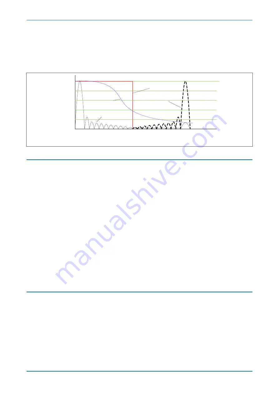
The following figure shows the nominal frequency response of the anti-alias filter and the Fourier filter for a 24-
sample single cycle fourier algorithm acting on the fundamental component:
Ideal anti-alias filter response
Real anti-alias filter
response
2 3 4
1
0.2
0.4
0.6
0.8
5 6 7 8 9 10 11 12 13
14 15 16 17 18 19 20 21 22 23 24
1
50 Hz
600 Hz
1200 Hz
V00301
Fourier response without
anti-alias filter
Fourier response with
anti-alias filter
Alias frequency
Figure 14: Frequency Response (indicative only)
5.4
PROGRAMMABLE SCHEME LOGIC
The purpose of the programmable scheme logic (PSL) is to allow you to configure your own protection schemes to
suit your particular application. This is done with programmable logic gates and delay timers. To allow greater
flexibility, different PSL is allowed for each of the four setting groups.
The input to the PSL is any combination of the status of the digital input signals from the opto-isolators on the
input board, the outputs of the protection elements such as protection starts and trips, and the outputs of the fixed
protection scheme logic (FSL). The fixed scheme logic provides the standard protection schemes. The PSL consists
of software logic gates and timers. The logic gates can be programmed to perform a range of different logic
functions and can accept any number of inputs. The timers are used either to create a programmable delay,
and/or to condition the logic outputs, such as to create a pulse of fixed duration on the output regardless of the
length of the pulse on the input. The outputs of the PSL are the LEDs on the front panel of the relay and the output
contacts at the rear.
The execution of the PSL logic is event driven. The logic is processed whenever any of its inputs change, for
example as a result of a change in one of the digital input signals or a trip output from a protection element. Also,
only the part of the PSL logic that is affected by the particular input change that has occurred is processed. This
reduces the amount of processing time that is used by the PSL. The protection & control software updates the logic
delay timers and checks for a change in the PSL input signals every time it runs.
The PSL can be configured to create very complex schemes. Because of this PSL desing is achieved by means of a
PC support package called the PSL Editor. This is available as part of the settings application software MiCOm S1
Agile, or as a standalone software module.
5.5
EVENT RECORDING
A change in any digital input signal or protection element output signal is used to indicate that an event has taken
place. When this happens, the protection and control task sends a message to the supervisor task to indicate that
an event is available to be processed and writes the event data to a fast buffer controlled by the supervisor task.
When the supervisor task receives an event record, it instructs the platform software to create the appropriate log
in non-volatile memory (flash memory). The operation of the record logging to SRAM is slower than the supervisor
buffer. This means that the protection software is not delayed waiting for the records to be logged by the platform
software. However, in the rare case when a large number of records to be logged are created in a short period of
time, it is possible that some will be lost, if the supervisor buffer is full before the platform software is able to create
a new log in SRAM. If this occurs then an event is logged to indicate this loss of information.
P24xM
Chapter 4 - Software Design
P24xM-TM-EN-2.1
51
Содержание P24DM
Страница 2: ......
Страница 17: ...Appendix C Wiring Diagrams 467 P24xM Contents P24xM TM EN 2 1 xv...
Страница 18: ...Contents P24xM xvi P24xM TM EN 2 1...
Страница 24: ...Table of Figures P24xM xxii P24xM TM EN 2 1...
Страница 25: ...CHAPTER 1 INTRODUCTION...
Страница 26: ...Chapter 1 Introduction P24xM 2 P24xM TM EN 2 1...
Страница 37: ...CHAPTER 2 SAFETY INFORMATION...
Страница 38: ...Chapter 2 Safety Information P24xM 14 P24xM TM EN 2 1...
Страница 51: ...CHAPTER 3 HARDWARE DESIGN...
Страница 52: ...Chapter 3 Hardware Design P24xM 28 P24xM TM EN 2 1...
Страница 66: ...Chapter 3 Hardware Design P24xM 42 P24xM TM EN 2 1...
Страница 67: ...CHAPTER 4 SOFTWARE DESIGN...
Страница 68: ...Chapter 4 Software Design P24xM 44 P24xM TM EN 2 1...
Страница 77: ...CHAPTER 5 CONFIGURATION...
Страница 78: ...Chapter 5 Configuration P24xM 54 P24xM TM EN 2 1...
Страница 94: ...Chapter 5 Configuration P24xM 70 P24xM TM EN 2 1...
Страница 95: ...CHAPTER 6 CURRENT PROTECTION FUNCTIONS...
Страница 96: ...Chapter 6 Current Protection Functions P24xM 72 P24xM TM EN 2 1...
Страница 188: ...Chapter 6 Current Protection Functions P24xM 164 P24xM TM EN 2 1...
Страница 189: ...CHAPTER 7 RESTRICTED EARTH FAULT PROTECTION...
Страница 190: ...Chapter 7 Restricted Earth Fault Protection P24xM 166 P24xM TM EN 2 1...
Страница 201: ...CHAPTER 8 CB FAIL PROTECTION...
Страница 202: ...Chapter 8 CB Fail Protection P24xM 178 P24xM TM EN 2 1...
Страница 215: ...CHAPTER 9 CURRENT TRANSFORMER REQUIREMENTS...
Страница 216: ...Chapter 9 Current Transformer Requirements P24xM 192 P24xM TM EN 2 1...
Страница 224: ...Chapter 9 Current Transformer Requirements P24xM 200 P24xM TM EN 2 1...
Страница 225: ...CHAPTER 10 VOLTAGE PROTECTION FUNCTIONS...
Страница 226: ...Chapter 10 Voltage Protection Functions P24xM 202 P24xM TM EN 2 1...
Страница 245: ...CHAPTER 11 FREQUENCY PROTECTION FUNCTIONS...
Страница 246: ...Chapter 11 Frequency Protection Functions P24xM 222 P24xM TM EN 2 1...
Страница 261: ...CHAPTER 12 POWER PROTECTION FUNCTIONS...
Страница 262: ...Chapter 12 Power Protection Functions P24xM 238 P24xM TM EN 2 1...
Страница 265: ...CHAPTER 13 MONITORING AND CONTROL...
Страница 266: ...Chapter 13 Monitoring and Control P24xM 242 P24xM TM EN 2 1...
Страница 294: ...Chapter 13 Monitoring and Control P24xM 270 P24xM TM EN 2 1...
Страница 295: ...CHAPTER 14 SUPERVISION...
Страница 296: ...Chapter 14 Supervision P24xM 272 P24xM TM EN 2 1...
Страница 312: ...Chapter 14 Supervision P24xM 288 P24xM TM EN 2 1...
Страница 313: ...CHAPTER 15 DIGITAL I O AND PSL CONFIGURATION...
Страница 314: ...Chapter 15 Digital I O and PSL Configuration P24xM 290 P24xM TM EN 2 1...
Страница 327: ...CHAPTER 16 COMMUNICATIONS...
Страница 328: ...Chapter 16 Communications P24xM 304 P24xM TM EN 2 1...
Страница 386: ...Chapter 16 Communications P24xM 362 P24xM TM EN 2 1...
Страница 387: ...CHAPTER 17 CYBER SECURITY...
Страница 388: ...Chapter 17 Cyber Security P24xM 364 P24xM TM EN 2 1...
Страница 405: ...CHAPTER 18 INSTALLATION...
Страница 406: ...Chapter 18 Installation P24xM 382 P24xM TM EN 2 1...
Страница 418: ...A B B A A B B A E01464 Figure 166 40TE case dimensions Chapter 18 Installation P24xM 394 P24xM TM EN 2 1...
Страница 419: ...CHAPTER 19 COMMISSIONING INSTRUCTIONS...
Страница 420: ...Chapter 19 Commissioning Instructions P24xM 396 P24xM TM EN 2 1...
Страница 443: ...CHAPTER 20 MAINTENANCE AND TROUBLESHOOTING...
Страница 444: ...Chapter 20 Maintenance and Troubleshooting P24xM 420 P24xM TM EN 2 1...
Страница 453: ...CHAPTER 21 TECHNICAL SPECIFICATIONS...
Страница 454: ...Chapter 21 Technical Specifications P24xM 430 P24xM TM EN 2 1...
Страница 470: ...Disengagement Time 250 ms Note Tested at 21 C Chapter 21 Technical Specifications P24xM 446 P24xM TM EN 2 1...
Страница 486: ...Chapter 21 Technical Specifications P24xM 462 P24xM TM EN 2 1...
Страница 487: ...APPENDIX A ORDERING OPTIONS...
Страница 488: ...Appendix A Ordering Options P24xM 464 P24xM TM EN 2 1...
Страница 491: ...APPENDIX B SETTINGS AND SIGNALS...
Страница 493: ...APPENDIX C WIRING DIAGRAMS...
Страница 494: ...Appendix C Wiring Diagrams P24xM 468 P24xM TM EN 2 1...
Страница 497: ......
Страница 498: ......
Страница 499: ......
Страница 500: ......
Страница 501: ......
Страница 502: ......
Страница 503: ......
Страница 504: ......
Страница 505: ......
Страница 506: ......
Страница 507: ......
Страница 508: ......
Страница 509: ......
Страница 510: ......
Страница 511: ......
Страница 512: ......
Страница 513: ......
Страница 514: ......
Страница 515: ......
Страница 516: ......
Страница 517: ......
Страница 518: ......
Страница 519: ......
Страница 520: ......
Страница 521: ......
Страница 522: ......
Страница 523: ......
Страница 524: ......
Страница 525: ......
Страница 526: ......
Страница 527: ......
Страница 528: ......
Страница 529: ......
Страница 530: ......
Страница 531: ......
Страница 532: ......
Страница 533: ......
Страница 534: ......
Страница 535: ......
Страница 536: ......
Страница 537: ......
Страница 538: ......
Страница 539: ......
Страница 540: ......
Страница 541: ......
Страница 542: ......
Страница 543: ......
Страница 544: ......
Страница 545: ......
Страница 546: ......
Страница 547: ......
Страница 548: ......
Страница 549: ......
Страница 550: ......
Страница 551: ......
Страница 552: ......
Страница 553: ......
Страница 554: ......
Страница 555: ......
Страница 556: ......
Страница 557: ......
Страница 558: ......
Страница 559: ......
Страница 560: ......
Страница 561: ......
Страница 562: ......
Страница 563: ......
Страница 564: ......
Страница 565: ......
Страница 566: ......
Страница 567: ......
Страница 568: ......
Страница 569: ......
Страница 570: ......
Страница 571: ......
Страница 572: ......
Страница 573: ......
Страница 574: ......
Страница 575: ......
Страница 576: ......
Страница 577: ......
Страница 578: ......
Страница 579: ......
Страница 580: ......
Страница 581: ......
Страница 582: ......
Страница 583: ......
Страница 584: ......
Страница 585: ......
Страница 586: ......
Страница 587: ......
Страница 588: ......
Страница 589: ......
Страница 590: ......
Страница 591: ......
Страница 592: ......
Страница 593: ......
Страница 594: ......
Страница 595: ......
Страница 596: ......
Страница 597: ......
Страница 598: ......
Страница 599: ......


