


Note:
Discrimination can be provided without the need for directional control. This can only be achieved if it is possible to set the
relay in excess of the charging current of the protected feeder and below the charging current for the rest of the system.
Setting guidelines
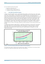
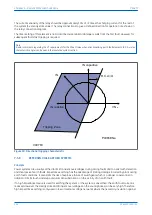
The residual current detected by the relay on the faulted feeder is equal to the sum of the charging currents
flowing from the rest of the system. The addition of the two healthy phase charging currents on each feeder gives
a total charging current which has a magnitude of three times the per phase value. Therefore, the total unbalance
current detected by the relay is equal to three times the per phase charging current of the rest of the system. A
typical relay setting can be 30% of this value, that is equal to the per phase charging current of the remaining
system. In practice, the required setting can be determined on site, where system faults can be applied and
suitable settings can be adopted based on practically obtained results. The use of P24xM relays comprehensive
measurement and fault recording facilities can prove very useful in this respect.
The timer setting of this element is not critical, since for the first fault only capacitive current exists on the system.
However, for subsequent faults, fast tripping is required. If the motor is operated using a fused contactor it is
important to delay the protection sufficiently to ensure that the contactor does not attempt to interrupt fault
current in excess of its breaking capacity.
7.5.6
RESISTANCE EARTHED SYSTEMS
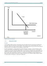
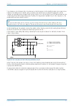
Earthing the system using a resistor reduces both the fault current and transient overvoltages. Resistance earthing
can sometimes be advantageous in hazardous environments such as in mines since the earthing resistance
reduces touch and step potentials during earth faults.
Setting guidelines
On a resistance earthed system, it is common practice to limit the fault current to approximately full load current.
For this type of application the relay can be set non-directional with a current sensitivity of less than 30% of the
minimum earth fault level, but greater than three times the steady state charging current of the motor feeder.
Guidelines given for solidly earthed systems are also applicable for the required time delay setting.
Note:
If the setting guidelines for applying a non-directional relay cannot be achieved due to the current magnitudes, then a
sensitive directional earth fault element is required. This eliminates the need to set the relay in excess of the charging current
for the protected feeder.
7.5.7
HIGH RESISTANCE EARTHING
For certain applications, the fault current can be severely limited by the use of very high resistance earthing. It is
usual in this case to choose a value of resistor which limits the resistive fault current to a similar magnitude as the
system charging current. Therefore, charging current has a marked influence on the angle of the fault current with
respect to the polarizing voltage (-3 Vo).
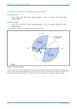
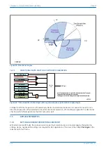
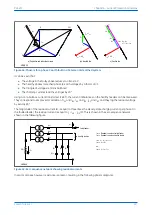
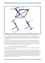
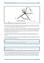
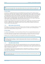
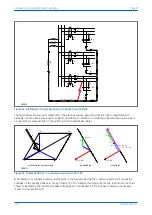
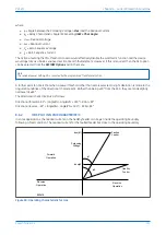
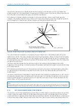
In this application sensitive directional earthfault protection, operated from a core balance CT, is required. The
relay characteristic angle setting should therefore be set to +45° (refer to the Phasor diagrams for insulated
system with C phase fault figure).
Note:
The recommended setting corresponds to the relay being connected so that its direction of current flow for operation is from
the motor feeder into the busbar.
P24xM
Chapter 6 - Current Protection Functions
P24xM-TM-EN-2.1
123
Содержание P24DM
Страница 2: ......
Страница 17: ...Appendix C Wiring Diagrams 467 P24xM Contents P24xM TM EN 2 1 xv...
Страница 18: ...Contents P24xM xvi P24xM TM EN 2 1...
Страница 24: ...Table of Figures P24xM xxii P24xM TM EN 2 1...
Страница 25: ...CHAPTER 1 INTRODUCTION...
Страница 26: ...Chapter 1 Introduction P24xM 2 P24xM TM EN 2 1...
Страница 37: ...CHAPTER 2 SAFETY INFORMATION...
Страница 38: ...Chapter 2 Safety Information P24xM 14 P24xM TM EN 2 1...
Страница 51: ...CHAPTER 3 HARDWARE DESIGN...
Страница 52: ...Chapter 3 Hardware Design P24xM 28 P24xM TM EN 2 1...
Страница 66: ...Chapter 3 Hardware Design P24xM 42 P24xM TM EN 2 1...
Страница 67: ...CHAPTER 4 SOFTWARE DESIGN...
Страница 68: ...Chapter 4 Software Design P24xM 44 P24xM TM EN 2 1...
Страница 77: ...CHAPTER 5 CONFIGURATION...
Страница 78: ...Chapter 5 Configuration P24xM 54 P24xM TM EN 2 1...
Страница 94: ...Chapter 5 Configuration P24xM 70 P24xM TM EN 2 1...
Страница 95: ...CHAPTER 6 CURRENT PROTECTION FUNCTIONS...
Страница 96: ...Chapter 6 Current Protection Functions P24xM 72 P24xM TM EN 2 1...
Страница 188: ...Chapter 6 Current Protection Functions P24xM 164 P24xM TM EN 2 1...
Страница 189: ...CHAPTER 7 RESTRICTED EARTH FAULT PROTECTION...
Страница 190: ...Chapter 7 Restricted Earth Fault Protection P24xM 166 P24xM TM EN 2 1...
Страница 201: ...CHAPTER 8 CB FAIL PROTECTION...
Страница 202: ...Chapter 8 CB Fail Protection P24xM 178 P24xM TM EN 2 1...
Страница 215: ...CHAPTER 9 CURRENT TRANSFORMER REQUIREMENTS...
Страница 216: ...Chapter 9 Current Transformer Requirements P24xM 192 P24xM TM EN 2 1...
Страница 224: ...Chapter 9 Current Transformer Requirements P24xM 200 P24xM TM EN 2 1...
Страница 225: ...CHAPTER 10 VOLTAGE PROTECTION FUNCTIONS...
Страница 226: ...Chapter 10 Voltage Protection Functions P24xM 202 P24xM TM EN 2 1...
Страница 245: ...CHAPTER 11 FREQUENCY PROTECTION FUNCTIONS...
Страница 246: ...Chapter 11 Frequency Protection Functions P24xM 222 P24xM TM EN 2 1...
Страница 261: ...CHAPTER 12 POWER PROTECTION FUNCTIONS...
Страница 262: ...Chapter 12 Power Protection Functions P24xM 238 P24xM TM EN 2 1...
Страница 265: ...CHAPTER 13 MONITORING AND CONTROL...
Страница 266: ...Chapter 13 Monitoring and Control P24xM 242 P24xM TM EN 2 1...
Страница 294: ...Chapter 13 Monitoring and Control P24xM 270 P24xM TM EN 2 1...
Страница 295: ...CHAPTER 14 SUPERVISION...
Страница 296: ...Chapter 14 Supervision P24xM 272 P24xM TM EN 2 1...
Страница 312: ...Chapter 14 Supervision P24xM 288 P24xM TM EN 2 1...
Страница 313: ...CHAPTER 15 DIGITAL I O AND PSL CONFIGURATION...
Страница 314: ...Chapter 15 Digital I O and PSL Configuration P24xM 290 P24xM TM EN 2 1...
Страница 327: ...CHAPTER 16 COMMUNICATIONS...
Страница 328: ...Chapter 16 Communications P24xM 304 P24xM TM EN 2 1...
Страница 386: ...Chapter 16 Communications P24xM 362 P24xM TM EN 2 1...
Страница 387: ...CHAPTER 17 CYBER SECURITY...
Страница 388: ...Chapter 17 Cyber Security P24xM 364 P24xM TM EN 2 1...
Страница 405: ...CHAPTER 18 INSTALLATION...
Страница 406: ...Chapter 18 Installation P24xM 382 P24xM TM EN 2 1...
Страница 418: ...A B B A A B B A E01464 Figure 166 40TE case dimensions Chapter 18 Installation P24xM 394 P24xM TM EN 2 1...
Страница 419: ...CHAPTER 19 COMMISSIONING INSTRUCTIONS...
Страница 420: ...Chapter 19 Commissioning Instructions P24xM 396 P24xM TM EN 2 1...
Страница 443: ...CHAPTER 20 MAINTENANCE AND TROUBLESHOOTING...
Страница 444: ...Chapter 20 Maintenance and Troubleshooting P24xM 420 P24xM TM EN 2 1...
Страница 453: ...CHAPTER 21 TECHNICAL SPECIFICATIONS...
Страница 454: ...Chapter 21 Technical Specifications P24xM 430 P24xM TM EN 2 1...
Страница 470: ...Disengagement Time 250 ms Note Tested at 21 C Chapter 21 Technical Specifications P24xM 446 P24xM TM EN 2 1...
Страница 486: ...Chapter 21 Technical Specifications P24xM 462 P24xM TM EN 2 1...
Страница 487: ...APPENDIX A ORDERING OPTIONS...
Страница 488: ...Appendix A Ordering Options P24xM 464 P24xM TM EN 2 1...
Страница 491: ...APPENDIX B SETTINGS AND SIGNALS...
Страница 493: ...APPENDIX C WIRING DIAGRAMS...
Страница 494: ...Appendix C Wiring Diagrams P24xM 468 P24xM TM EN 2 1...
Страница 497: ......
Страница 498: ......
Страница 499: ......
Страница 500: ......
Страница 501: ......
Страница 502: ......
Страница 503: ......
Страница 504: ......
Страница 505: ......
Страница 506: ......
Страница 507: ......
Страница 508: ......
Страница 509: ......
Страница 510: ......
Страница 511: ......
Страница 512: ......
Страница 513: ......
Страница 514: ......
Страница 515: ......
Страница 516: ......
Страница 517: ......
Страница 518: ......
Страница 519: ......
Страница 520: ......
Страница 521: ......
Страница 522: ......
Страница 523: ......
Страница 524: ......
Страница 525: ......
Страница 526: ......
Страница 527: ......
Страница 528: ......
Страница 529: ......
Страница 530: ......
Страница 531: ......
Страница 532: ......
Страница 533: ......
Страница 534: ......
Страница 535: ......
Страница 536: ......
Страница 537: ......
Страница 538: ......
Страница 539: ......
Страница 540: ......
Страница 541: ......
Страница 542: ......
Страница 543: ......
Страница 544: ......
Страница 545: ......
Страница 546: ......
Страница 547: ......
Страница 548: ......
Страница 549: ......
Страница 550: ......
Страница 551: ......
Страница 552: ......
Страница 553: ......
Страница 554: ......
Страница 555: ......
Страница 556: ......
Страница 557: ......
Страница 558: ......
Страница 559: ......
Страница 560: ......
Страница 561: ......
Страница 562: ......
Страница 563: ......
Страница 564: ......
Страница 565: ......
Страница 566: ......
Страница 567: ......
Страница 568: ......
Страница 569: ......
Страница 570: ......
Страница 571: ......
Страница 572: ......
Страница 573: ......
Страница 574: ......
Страница 575: ......
Страница 576: ......
Страница 577: ......
Страница 578: ......
Страница 579: ......
Страница 580: ......
Страница 581: ......
Страница 582: ......
Страница 583: ......
Страница 584: ......
Страница 585: ......
Страница 586: ......
Страница 587: ......
Страница 588: ......
Страница 589: ......
Страница 590: ......
Страница 591: ......
Страница 592: ......
Страница 593: ......
Страница 594: ......
Страница 595: ......
Страница 596: ......
Страница 597: ......
Страница 598: ......
Страница 599: ......


