Setting guidelines
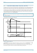
The stall current threshold (Stall Setting) should be set greater than full load current, but less than motor stall
current (which is usually equal to starting current). Its corresponding timer (Stall Time) should be set less than the
motor hot stall withstand time. The Stall Detection needs to be set to
Enabled
for this function to operate.
Setting example:
Utilizing the previously specified motor parameters;
Stall Setting = 3 x I
th
= 882 A
Stall Time = 6 seconds
14.8.4
EXCESSIVE START TIME/LOCKED ROTOR PROTECTION - STALL TIME < START TIME
As the rotor resistance of an induction motor is proportional to slip, it decreases during acceleration. When the
motor is stationary, the rotating field in the air gap, set up by currents flowing in the stator winding will cut the
rotor. This field travels at synchronous speed relative to the rotor and induces a voltage at system frequency,
therefore generating circulating currents in the rotor bars. At this frequency, the reactance of the rotor causes the
current to flow in the outer section of the rotor conductors, commonly known as the 'skin effect'. Since the current
is occupying a smaller section of the rotor, the apparent impedance presented to it is increased, which means the
I
2
R heating is greatly increased. As the motor accelerates during starting the slip begins to decrease and the
current is able to occupy more of the rotor conductor. The apparent impedance therefore reduces along with the
heating effect. The motor is able to tolerate starting current for the starting time, but not locked rotor current.
This explains why, for certain applications, such as motors driving high inertia loads, the stall withstand time can
be safely exceeded during starting, without resulting in an overtemperature condition within the motor. Since the
stall withstand time is less than the start time, it is not possible to use time alone to distinguish between a start
and a stall condition.
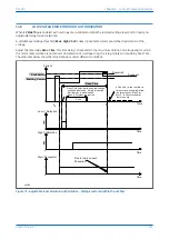
Where the stall withstand time is less than the starting time, it is possible to utilize a contact from a speed sensing
device wired into a specified opto input (Speed Input) in conjunction with measurement of the phase current to
detect a safe start.
Setting guidelines
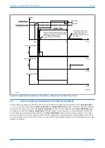
The Starting current threshold (Starting current) should be set greater than full load current, but less than motor
locked rotor current (usually equal to starting current). Its corresponding timer (Stall Time) should be set less than
the motor cold stall withstand time. The Stall Rotor-strt needs to be set to
Enabled
for this function to operate.
14.8.5
MOMENTARY REDUCTION IN SYSTEM VOLTAGE DURING RUNNING OF THE MOTOR
When the supply voltage falls below a settable under voltage threshold, the duration of the fall in voltage can be
classified as short, medium, or long. This corresponds with Reac. Time, Reac. Long Time and Reac. Shed Time
respectively of P24DM relay designations.
●
Short falls cover situations when it is appropriate to authorize reacceleration of the rotor and not to issue a
trip order after voltage restoration is detected using a settable under voltage threshold.
●
Medium falls cover situations when the voltage has not been recovered within a set short time. This is
detected using a settable over voltage threshold and the motor has tripped as a result. Therefore, it is
appropriate to automatically restart the motor within a set long time after the voltage has become restored.
Detection of restored voltage is based on a settable over voltage threshold.
●
Long falls cover cases when restoration is from back-up power and there must be substantial intervals
between starting different motors to maintain stability, and/or only critical motors can be started.
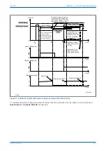
A short fall in voltage from the electrical network causes a reduction in rotor speed. If the motor was running at the
time a short fall occurred, a forced reacceleration occurs as soon as the relay detects healthy supply voltage. A
forced reacceleration bypasses any pre-staged start-up sequence the starter type might otherwise provide.
Chapter 6 - Current Protection Functions
P24xM
156
P24xM-TM-EN-2.1
Содержание P24DM
Страница 2: ......
Страница 17: ...Appendix C Wiring Diagrams 467 P24xM Contents P24xM TM EN 2 1 xv...
Страница 18: ...Contents P24xM xvi P24xM TM EN 2 1...
Страница 24: ...Table of Figures P24xM xxii P24xM TM EN 2 1...
Страница 25: ...CHAPTER 1 INTRODUCTION...
Страница 26: ...Chapter 1 Introduction P24xM 2 P24xM TM EN 2 1...
Страница 37: ...CHAPTER 2 SAFETY INFORMATION...
Страница 38: ...Chapter 2 Safety Information P24xM 14 P24xM TM EN 2 1...
Страница 51: ...CHAPTER 3 HARDWARE DESIGN...
Страница 52: ...Chapter 3 Hardware Design P24xM 28 P24xM TM EN 2 1...
Страница 66: ...Chapter 3 Hardware Design P24xM 42 P24xM TM EN 2 1...
Страница 67: ...CHAPTER 4 SOFTWARE DESIGN...
Страница 68: ...Chapter 4 Software Design P24xM 44 P24xM TM EN 2 1...
Страница 77: ...CHAPTER 5 CONFIGURATION...
Страница 78: ...Chapter 5 Configuration P24xM 54 P24xM TM EN 2 1...
Страница 94: ...Chapter 5 Configuration P24xM 70 P24xM TM EN 2 1...
Страница 95: ...CHAPTER 6 CURRENT PROTECTION FUNCTIONS...
Страница 96: ...Chapter 6 Current Protection Functions P24xM 72 P24xM TM EN 2 1...
Страница 188: ...Chapter 6 Current Protection Functions P24xM 164 P24xM TM EN 2 1...
Страница 189: ...CHAPTER 7 RESTRICTED EARTH FAULT PROTECTION...
Страница 190: ...Chapter 7 Restricted Earth Fault Protection P24xM 166 P24xM TM EN 2 1...
Страница 201: ...CHAPTER 8 CB FAIL PROTECTION...
Страница 202: ...Chapter 8 CB Fail Protection P24xM 178 P24xM TM EN 2 1...
Страница 215: ...CHAPTER 9 CURRENT TRANSFORMER REQUIREMENTS...
Страница 216: ...Chapter 9 Current Transformer Requirements P24xM 192 P24xM TM EN 2 1...
Страница 224: ...Chapter 9 Current Transformer Requirements P24xM 200 P24xM TM EN 2 1...
Страница 225: ...CHAPTER 10 VOLTAGE PROTECTION FUNCTIONS...
Страница 226: ...Chapter 10 Voltage Protection Functions P24xM 202 P24xM TM EN 2 1...
Страница 245: ...CHAPTER 11 FREQUENCY PROTECTION FUNCTIONS...
Страница 246: ...Chapter 11 Frequency Protection Functions P24xM 222 P24xM TM EN 2 1...
Страница 261: ...CHAPTER 12 POWER PROTECTION FUNCTIONS...
Страница 262: ...Chapter 12 Power Protection Functions P24xM 238 P24xM TM EN 2 1...
Страница 265: ...CHAPTER 13 MONITORING AND CONTROL...
Страница 266: ...Chapter 13 Monitoring and Control P24xM 242 P24xM TM EN 2 1...
Страница 294: ...Chapter 13 Monitoring and Control P24xM 270 P24xM TM EN 2 1...
Страница 295: ...CHAPTER 14 SUPERVISION...
Страница 296: ...Chapter 14 Supervision P24xM 272 P24xM TM EN 2 1...
Страница 312: ...Chapter 14 Supervision P24xM 288 P24xM TM EN 2 1...
Страница 313: ...CHAPTER 15 DIGITAL I O AND PSL CONFIGURATION...
Страница 314: ...Chapter 15 Digital I O and PSL Configuration P24xM 290 P24xM TM EN 2 1...
Страница 327: ...CHAPTER 16 COMMUNICATIONS...
Страница 328: ...Chapter 16 Communications P24xM 304 P24xM TM EN 2 1...
Страница 386: ...Chapter 16 Communications P24xM 362 P24xM TM EN 2 1...
Страница 387: ...CHAPTER 17 CYBER SECURITY...
Страница 388: ...Chapter 17 Cyber Security P24xM 364 P24xM TM EN 2 1...
Страница 405: ...CHAPTER 18 INSTALLATION...
Страница 406: ...Chapter 18 Installation P24xM 382 P24xM TM EN 2 1...
Страница 418: ...A B B A A B B A E01464 Figure 166 40TE case dimensions Chapter 18 Installation P24xM 394 P24xM TM EN 2 1...
Страница 419: ...CHAPTER 19 COMMISSIONING INSTRUCTIONS...
Страница 420: ...Chapter 19 Commissioning Instructions P24xM 396 P24xM TM EN 2 1...
Страница 443: ...CHAPTER 20 MAINTENANCE AND TROUBLESHOOTING...
Страница 444: ...Chapter 20 Maintenance and Troubleshooting P24xM 420 P24xM TM EN 2 1...
Страница 453: ...CHAPTER 21 TECHNICAL SPECIFICATIONS...
Страница 454: ...Chapter 21 Technical Specifications P24xM 430 P24xM TM EN 2 1...
Страница 470: ...Disengagement Time 250 ms Note Tested at 21 C Chapter 21 Technical Specifications P24xM 446 P24xM TM EN 2 1...
Страница 486: ...Chapter 21 Technical Specifications P24xM 462 P24xM TM EN 2 1...
Страница 487: ...APPENDIX A ORDERING OPTIONS...
Страница 488: ...Appendix A Ordering Options P24xM 464 P24xM TM EN 2 1...
Страница 491: ...APPENDIX B SETTINGS AND SIGNALS...
Страница 493: ...APPENDIX C WIRING DIAGRAMS...
Страница 494: ...Appendix C Wiring Diagrams P24xM 468 P24xM TM EN 2 1...
Страница 497: ......
Страница 498: ......
Страница 499: ......
Страница 500: ......
Страница 501: ......
Страница 502: ......
Страница 503: ......
Страница 504: ......
Страница 505: ......
Страница 506: ......
Страница 507: ......
Страница 508: ......
Страница 509: ......
Страница 510: ......
Страница 511: ......
Страница 512: ......
Страница 513: ......
Страница 514: ......
Страница 515: ......
Страница 516: ......
Страница 517: ......
Страница 518: ......
Страница 519: ......
Страница 520: ......
Страница 521: ......
Страница 522: ......
Страница 523: ......
Страница 524: ......
Страница 525: ......
Страница 526: ......
Страница 527: ......
Страница 528: ......
Страница 529: ......
Страница 530: ......
Страница 531: ......
Страница 532: ......
Страница 533: ......
Страница 534: ......
Страница 535: ......
Страница 536: ......
Страница 537: ......
Страница 538: ......
Страница 539: ......
Страница 540: ......
Страница 541: ......
Страница 542: ......
Страница 543: ......
Страница 544: ......
Страница 545: ......
Страница 546: ......
Страница 547: ......
Страница 548: ......
Страница 549: ......
Страница 550: ......
Страница 551: ......
Страница 552: ......
Страница 553: ......
Страница 554: ......
Страница 555: ......
Страница 556: ......
Страница 557: ......
Страница 558: ......
Страница 559: ......
Страница 560: ......
Страница 561: ......
Страница 562: ......
Страница 563: ......
Страница 564: ......
Страница 565: ......
Страница 566: ......
Страница 567: ......
Страница 568: ......
Страница 569: ......
Страница 570: ......
Страница 571: ......
Страница 572: ......
Страница 573: ......
Страница 574: ......
Страница 575: ......
Страница 576: ......
Страница 577: ......
Страница 578: ......
Страница 579: ......
Страница 580: ......
Страница 581: ......
Страница 582: ......
Страница 583: ......
Страница 584: ......
Страница 585: ......
Страница 586: ......
Страница 587: ......
Страница 588: ......
Страница 589: ......
Страница 590: ......
Страница 591: ......
Страница 592: ......
Страница 593: ......
Страница 594: ......
Страница 595: ......
Страница 596: ......
Страница 597: ......
Страница 598: ......
Страница 599: ......

