GE LOGIQ S7 Expert Скачать руководство пользователя страница 137

GE H

EALTHCARE

DRAFT

LOGIQ™ S7 E

XPERT

/P

RO

D

IRECTION


5460683

, R

EVISION


3

DRAFT (J

UNE

 25, 2014)

 S

ERVICE

 M

ANUAL

Chapter 4 - Functional Checks

4-15

4-3-3-4

Complete power down


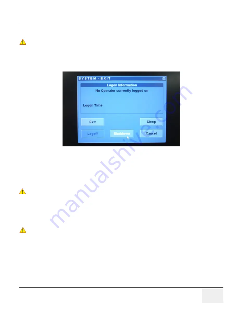
1.) If not already in read mode, freeze the image.

2.) When you shutdown the system, enter the scan screen and lightly press the Power On/Off switch 

(see: 

Figure 4-14

) once. The System-Exit window is displayed.

Figure 4-14   Power OFF User Interface

3.) Select the SHUTDOWN button. The system performs an automatic full shutdown sequence.

4.) Switch OFF the Circuit Breaker at the rear of the system.

NOTE:

The mains outlet of the system for peripheral auxiliary equipment are commonly switched with the ON/
OFF
 button. So the auxiliary equipment need not to be switched ON/OFF separately.

5.) After complete power down, unscrew the 2 screws and remove the pull-out protection to disconnect 

the main power cable from the system or unplug it from the AC wall outlet socket.

6.) Press on the brakes to block the front caster wheels.

7.) Disconnect probes. 

NOTICE

!! NOTICE:

After turning off a system, wait at least 10 seconds before turning it on again. The system may not be 
able to boot if power is recycled too quickly.

WARNING

WARNING

!! WARNING:

Disconnection of the Main Power Cable is necessary!
For Example: When repairing the system.

NOTICE

!! NOTICE:

Be sure to follow probe handling instruction and caution outlined in Basic User Manual.

Содержание LOGIQ S7 Expert

Страница 1: ...RVICE DOCUMENTATION PROPERTY OF GE HEALTHCARE USE OF THESE MATERIALS LIMITED TO AGENTS AND EMPLOYEES OF GE HEALTHCARE OR OTHER PARTIES EXPRESSLY LICENSED BY GE HEALTHCARE UNLICENSED USE IS STRICTLY PROHIBITED LOGIQ S7 Expert Pro Service Manual Document Number 5460683 Revision 3 ...

Страница 2: ......

Страница 3: ... QUE L ANGLAIS C EST AU CLIENT QU IL INCOMBE DE LE FAIRE TRADUIRE NE PAS TENTER D INTERVENTION SUR LES éQUIPEMENTS TANT QUE LE MANUEL SERVICE N A PAS éTé CONSULTé ET COMPRIS LE NON RESPECT DE CET AVERTISSEMENT PEUT ENTRAîNER CHEZ LE TECHNICIEN L OPéRATEUR OU LE PATIENT DES BLESSURES DUES à DES DANGERS éLECTRIQUES MéCANIQUES OU AUTRES DIESES KUNDENDIENST HANDBUCH EXISTIERT NUR IN ENGLISCHER SPRACHE...

Страница 4: ...U PACIENTE DEVIDO A CHOQUES ELéTRICOS MECâ NICOS OU OUTROS ESTE MANUAL DE ASSISTÊNCIA ESTÁ DISPONÍVEL APENAS EM INGLÊS SE QUALQUER OUTRO SERVIÇO DE ASSISTÊNCIA TÉCNICA QUE NÃO A GEHC SOLICITAR ESTES MANUAIS NOUTRO IDIOMA É DA RESPONSABILIDADE DO CLIENTE FORNECER OS SERVIÇOS DE TRADUÇÃO NÃO TENTE EFECTUAR REPARAÇÕES NO EQUIPAMENTO SEM TER CONSULTADO E COMPREENDIDO PREVIAMENTE ESTE MANUAL A INOBSERV...

Страница 5: ...Jä N TAI POTILAAN VAHINGOITTUMINEN Sä HKö ISKUN MEKAANISEN VIAN TAI MUUN VAARATILANTEEN VUOKSI ΤΟ ΠΑΡΟΝ ΕΓΧΕΙΡΙ ΙΟ ΣΕΡΒΙΣ ΙΑΤΙΘΕΤΑΙ ΣΤΑ ΑΓΓΛΙΚΑ ΜΟΝΟ ΕΑΝ ΤΟ ΑΤΟΜΟ ΠΑΡΟΧΗΣ ΣΕΡΒΙΣ ΕΝΟΣ ΠΕΛΑΤΗ ΑΠΑΙΤΕΙ ΤΟ ΠΑΡΟΝ ΕΓΧΕΙΡΙ ΙΟ ΣΕ ΓΛΩΣΣΑ ΕΚΤΟΣ ΤΩΝ ΑΓΓΛΙΚΩΝ ΑΠΟΤΕΛΕΙ ΕΥΘΥΝΗ ΤΟΥ ΠΕΛΑΤΗ ΝΑ ΠΑΡΕΧΕΙ ΥΠΗΡΕΣΙΕΣ ΜΕΤΑΦΡΑΣΗΣ ΜΗΝ ΕΠΙΧΕΙΡΗΣΕΤΕ ΤΗΝ ΕΚΤΕΛΕΣΗ ΕΡΓΑΣΙΩΝ ΣΕΡΒΙΣ ΣΤΟΝ ΕΞΟΠΛΙΣΜΟ ΕΚΤΟΣ ΕΑΝ ΕΧΕΤΕ ΣΥΜΒΟΥΛΕΥΤΕΙ ΚΑΙ Ε...

Страница 6: ...íKA POSKYTOVATELE SLUŽEB OBSLUŽNéHO PERSONá LU NEBO PACIENTů VLIVEM ELEKTRICKéHOP PROUDU RESPEKTIVE VLIVEM K RIZIKU MECHANICKÉHO POŠKOZENÍ NEBO JINÉMU RIZIKU DENNE SERVICEMANUAL FINDES KUN PÅ ENGELSK HVIS EN KUNDES TEKNIKER HAR BRUG FOR ET ANDET SPROG END ENGELSK ER DET KUNDENS ANSVAR AT SØRGE FOR OVERSÆTTELSE FORSØG IKKE AT SERVICERE UDSTYRET MEDMINDRE DENNE SERVICEMANUAL ER BLEVET LÆST OG FORSTÅ...

Страница 7: ...LI BŪTI SUŽEISTAS DĖL ELEKTROS SMŪGIO MECHANINIŲ AR KITŲ PAVOJŲ DENNE SERVICEHÅNDBOKEN FINNES BARE PÅ ENGELSK HVIS KUNDENS SERVICELEVERANDØR TRENGER ET ANNET SPRÅK ER DET KUNDENS ANSVAR Å SØRGE FOR OVERSETTELSE IKKE FORSØK Å REPARERE UTSTYRET UTEN AT DENNE SERVICEHÅNDBOKEN ER LEST OG FORSTÅTT MANGLENDE HENSYN TIL DENNE ADVARSELEN KAN FØRE TIL AT SERVICELEVERANDØREN OPERATØREN ELLER PASIENTEN SKADE...

Страница 8: ... ПРИВЕСТИ К ТОМУ ЧТО СПЕЦИАЛИСТ ПО ТЕХОБСЛУЖИВАНИЮ ОПЕРАТОР ИЛИ ПАЦИЕНТ ПОЛУЧАТ УДАР ЗЛЕКТРИЧЕСКИМ ТОКОМ МЕХАНИЧЕСКУЮ ТРАВМУ ИЛИ ДРУГОЕ ПОВРЕЖДЕНИЕ ТОВА СЕРВИЗНО РЪКОВОДСТВО Е НАЛИЧНО САМО НА АНГЛИЙСКИ ЕЗИК АКО ДОСТАВЧИКЪТ НА СЕРВИЗНИ УСЛУГИ НА КЛИЕНТ СЕ НУЖДАЕ ОТ ЕЗИК РАЗЛИЧЕН ОТ АНГЛИЙСКИ ЗАДЪЛЖЕНИЕ НА КЛИЕНТА Е ДА ПРЕДОСТАВИ ПРЕВОДАЧЕСКА УСЛУГА НЕ СЕ ОПИТВАЙТЕ ДА ИЗВЪРШВАТЕ СЕРВИЗНО ОБСЛУЖВАНЕ ...

Страница 9: ...PROUZROČENE STRUJNIM UDAROM MEHANIČKIM I DRUGIM OPASNOSTIMA TÁTO SERVISNÁ PRÍRUČKA JE K DISPOZíCII LEN V ANGLIČTINE AK ZÁKAZNÍKOV POSKYTOVATEĽ SLUŽIEB VYŽADUJE INÝ JAZYK AKO ANGLIČTINU POSKYTNUTIE PREKLADATEĽSKÝCH SLUŽIEB JE ZODPOVEDNOSŤOU ZÁKAZNÍKA NEPOKÚŠAJTE SA VYKONÁVAŤ SERVIS ZARIADENIA SKÔR AKO SI NEPREČÍTATE SERVISNÚ PRÍRUČKU A NEPOROZUMIETE JEJ ZANEDBANIE TOHTO UPOZORNENIA Mô ŽE VYÚSTIŤ DO...

Страница 10: ...AVUZUN İNGİLİZCE DIŞINDAKİ BİR DİLDE OLMASINI İSTERSE KILAVUZU TERCÜME ETTİRMEK MÜŞTERİNİN SORUMLULUĞUNDADIR SERVİS KILAVUZUNU OKUYUP ANLAMADAN EKİPMANLARA MÜDAHALE ETMEYİNİZ BU UYARININ GÖZ ARDI EDİLMESİ ELEKTRİK ÇARPMASI YA DA MEKANİK VEYA DİĞER TÜRDEN KAZALAR SONUCUNDA TEKNİSYENİN OPERATÖRÜN YA DA HASTANIN YARALANMASINA YOL AÇABİLİR DİKKAT TR JA Traditional Chinese ...

Страница 11: ...GE HEALTHCARE LOGIQ S7 EXPERT PRO DIRECTION 5460683 REVISION 3 SERVICE MANUAL ix ZH CN KO ...

Страница 12: ... All of GE s electrical work on these products will comply with the requirements of the applicable electrical codes The purchaser of GE equipment shall only utilize qualified personnel i e GE s field engineers personnel of third party service companies with equivalent training or licensed electricians to perform electrical servicing on the equipment OMISSIONS ERRORS If there are any omissions erro...

Страница 13: ...licated in any form in whole or in part without prior written permission of GE Healthcare GE Healthcare may revise this publication from time to time without written notice TRADEMARKS All products and their name brands are trademarks of their respective holders COPYRIGHTS All Material Copyright 2011 by General Electric Company Inc All Rights Reserved ...

Страница 14: ...1 July 2012 Initial release 2 August 2012 Had some feedback from Service team 3 June 2014 Updated for R2 x x or later Pages Revision Pages Revision Pages Revision Title Page 3 3 1 to 3 60 3 8 1 to 8 144 3 Warnings i to ii xii 3 4 1 to 4 34 3 9 1 to 9 24 3 TOC 3 5 1 to 5 40 3 10 1 to 10 36 3 1 1 to 1 14 3 6 1 to 6 8 3 Back Cover N A 2 1 to 2 10 3 7 1 to 7 24 3 ...

Страница 15: ...andard Hazard Icons 1 4 Product Icons 1 5 Safety Considerations 1 7 Introduction 1 7 Human Safety 1 7 Mechanical Safety 1 7 Electrical Safety 1 8 Safe Practices 1 8 Probes 1 8 Auxiliary Devices Safety 1 8 Battery Safety R2 x x or later 1 10 Labels Locations 1 11 Dangerous Procedure Warnings 1 12 Lockout Tagout Requirements For USA Only 1 12 Returning Shipping System Probes and Repair Parts 1 12 El...

Страница 16: ...n Power Plug 2 3 EMI Limitations 2 4 Probe Environmental Requirements Time and Manpower Requirements 2 5 System Specifications 2 6 Physical Dimensions of LOGIQ S7 Expert Pro 2 6 Acoustic Noise Output 2 6 Electrical Specifications 2 6 Facility Needs 2 7 Purchaser Responsibilities 2 7 Mandatory Site Requirements 2 8 Site Recommendations 2 8 Recommended Ultrasound Room Layout 2 9 Networking Setup Req...

Страница 17: ...on of Auxiliary Devices 3 10 Connecting the LCD Monitor 3 11 Connecting the Black White Printer 3 12 Connection Scheme B W Printer 3 13 Connecting the Color Printer 3 14 Connection Scheme Color Printer 3 15 Connecting the Secondary Patient LCD Monitor 3 16 Connecting the Footswitch 3 18 Connecting the USB Flash Memory Stick 3 19 Connecting the external USB Hard disk Handydrive 3 19 General Remarks...

Страница 18: ... Officejet 100 3 33 Bluetooth Pairing 3 33 Adding Printer to the system 3 34 Adjustment of Printer Settings 3 34 UP D897 Printer Settings 3 35 UP D25MD Printer Settings 3 36 Setting Printer to Print Reports 3 38 Setting up the Printer to Print Reports 3 38 System Configuration 3 39 System General Preset Menu 3 39 External I O Connectors 3 42 Available Probes 3 43 Supported probes 3 43 Probe Naming...

Страница 19: ...utlet on the hospital s network 3 50 Connection using Wireless Option R2 x x or later 3 50 Configuring Connectivity 3 51 Overview 3 51 Structured Reporting 3 51 Supported parameters 3 51 Connectivity Functions 3 52 TCPIP 3 53 Device 3 55 Service 3 56 Adding a service to a destination device 3 56 Removing a service 3 56 Changing parameters for a service 3 57 Connectivity Setup Worksheet 3 58 Paperw...

Страница 20: ... On Off Scanner Power On 4 11 Sleep Mode Check R1 x x 4 13 Sleep Mode Check R2 x x or later 4 14 Complete power down 4 15 Power Off Shutdown Check 4 16 System Information 4 17 Software Version 4 17 Service Platform Confirmation 4 18 USB Port Test 4 19 System Integration Checks 4 20 OPIO Test 4 20 DVD Drive Test 4 21 LAN Port Test 4 21 Peripheral Checks 4 22 DVR Test if equipped 4 22 Black and Whit...

Страница 21: ...GE HEALTHCARE LOGIQ S7 EXPERT PRO DIRECTION 5460683 REVISION 3 SERVICE MANUAL Table of Contents xix M Mode 4 26 B Flow Mode 4 26 OPIO Interface Check 4 28 Board Diagnostics 4 32 ...

Страница 22: ...niJack 5 10 AC Inlet 5 10 Power ON Sequence 5 11 Software Options 5 18 Options 5 18 Hardware Options 5 20 Options 5 20 Regional and Peripheral Options 5 22 Regional Options 5 22 Peripheral Options 5 22 Mechanical Descriptions 5 24 Physical Dimensions 5 24 LCD Monitor 5 24 OPIO Positioning 5 24 Air Flow Distribution 5 25 Exiting to Windows Desktop 5 26 Exiting to Windows Desktop 5 26 Service Platfo...

Страница 23: ... Contents xxi Common Service Desktop CSD 5 30 Internationalization 5 30 CSD Top Page 5 31 General Layout 5 31 Decoding System Temperature and Voltage 5 32 Error Logs 5 34 Diagnostics 5 34 Image Quality 5 35 Configuration 5 36 Utilities 5 37 Disk Defragmenter 5 37 Replacement 5 39 PM 5 39 ...

Страница 24: ...view 6 1 Purpose of Chapter 6 6 1 Regulatory 6 1 LCD Monitor Adjustment 6 2 Brightness Contrast 6 3 Brightness 6 3 Contrast 6 4 Gamma 6 4 Mode 6 4 Function 6 5 Scale 6 5 Information 6 5 Memory Recall 6 6 SBC 6 6 OSD 6 7 Language 6 7 H Position 6 7 V Postion 6 7 Half Tone 6 7 Exit 6 8 OSD Control on the Utility mode R2 x x or later 6 8 ...

Страница 25: ...reen 7 8 Export Log s and System Data 7 8 Export System Data by pressing the ALT D key 7 8 System Warning Errors and Logs 7 9 Temperature warning 7 9 Cause 7 9 What to do 7 9 Temperature exceeded threshold 7 9 Cause 7 9 What to do 7 9 Log message of the high temperature 7 9 System voltage failure 7 10 Cause 7 10 What to Do 7 10 Log message of the Voltage error 7 10 Hardware configuration error 7 1...

Страница 26: ...GE Service Technician 7 16 If GE Service Technician requests Remote Access Permission 7 16 Common Service Desktop CSD 7 17 CSD Configuration 7 17 Minimum Configuration to Boot Scan 7 18 Troubleshooting Trees Instructions and Tech Tips 7 19 System does not boot up 7 20 Noise disturbs the Image 7 21 Trackball Impaired Sensitivity 7 22 Printer Malfunction 7 23 Monitor Troubleshooting 7 24 ...

Страница 27: ...8 7 Recording important settings and parameters optional 8 7 System Software Installation Procedure 8 19 Software Installation from DVD 8 19 System Software Installation Procedure R1 x x 8 19 System Software Installation Procedure R2 x x or later 8 21 Application Software Installation Preparation 8 25 Application Software Installation 8 26 Software Installation from Common Service Desktop 8 29 Inv...

Страница 28: ...41 Removal Procedure 8 41 Removal Procedure Side Cover L 8 41 Removal Procedure Side Cover R 8 43 Installation Procedure 8 44 Functional Check 8 44 Replacement Rear Cover 8 45 Manpower 8 45 Tools 8 45 Removal Procedure 8 45 Installation Procedure 8 45 Functional Check 8 45 Replacement Side Tray Footrest Cover 8 46 Manpower 8 46 Tools 8 46 Removal Procedure 8 46 Removal Procedure Side Tray 8 46 Rem...

Страница 29: ... Removal Procedure TGC Assy 8 58 Removal Procedure LCD Touch Panel Assy 8 59 Removal Procedure Sub Board Assy 8 59 Removal Procedure OP Panel Main PWA Assy 8 60 Removal Procedure Joystick Assy 8 60 Removal Procedure Joystick and Encoder on PWA 8 61 Installation Procedure 8 62 Functional Check Replacement of the Caps for Hardkeys 8 63 Manpower 8 63 Tools 8 63 Removal Procedure 8 63 Installation Pro...

Страница 30: ... Procedure Separating CBP Backplane 8 81 Installation Procedure CBP 8 81 Functional Check 8 81 Replacement of CPS2 R2 x x or later 8 82 Manpower 8 82 Tools 8 82 Removal Procedure 8 82 Installation Procedure 8 84 Functional Check 8 84 Replacement of CSI and Fan 8 85 Manpower 8 85 Tools 8 85 Removal Procedure 8 85 Installation Procedure 8 87 Functional Check 8 87 Replacement of Rear Handle 8 88 Manp...

Страница 31: ...allation Procedure 8 103 Functional Check 8 103 Replacement of 4D 8 104 Manpower 8 104 Tools 8 104 Removal Procedure 8 104 Installation Procedure 8 104 Functional Check 8 104 Replacement of Wireless Lan 8 105 Manpower 8 105 Tools 8 105 Removal Procedure 8 105 Installation Procedure 8 106 Functional Check 8 106 Replacement of the Harness Cable Cable Duct and OPIO Cable Assy 8 107 Manpower 8 107 Too...

Страница 32: ...oval Procedure Cable Hook 8 118 Removal Procedure Extended Probe Holder 8 119 Installation Procedure 8 119 Functional Check 8 119 Replacement of AC Cable Holder 8 120 Manpower 8 120 Tools 8 120 Removal Procedure 8 120 Installation Procedure 8 120 Functional Check Replacement of the Peripherals 8 121 B W Printer 8 121 B W on Mid High Console 8 121 Manpower 8 121 Tools 8 121 Removal Procedure 8 121 ...

Страница 33: ... Functional Check 8 129 Replacement of the Monitor Arm 8 130 Manpower 8 130 Tools 8 130 Removal Procedure 8 130 Installation Procedure 8 134 Functional Check 8 134 Replacement of Filter 8 134 Manpower 8 134 Tools 8 134 Removal Procedure 8 134 Installation Procedure 8 134 Functional Check 8 134 Replacement of SW CD set 8 134 Manpower 8 134 Tools 8 134 Removal Procedure 8 134 Installation Procedure ...

Страница 34: ...ment ECG Module 8 139 ECG Module 8 139 Manpower 8 139 Tools 8 139 Removal Procedure 8 139 Installation Procedure 8 139 Functional Check 8 139 Replacement of UVC 8 140 UVC ASSY 8 140 Manpower 8 140 Tools 8 140 Removal Procedure 8 140 Installation Procedure 8 142 Functional Check 8 142 Replacement of DCWD ASSY 8 143 DCWD ASSY 8 143 Manpower 8 143 Tools 8 143 8 32 1 3 Removal procedure 8 143 Installa...

Страница 35: ...CHAPTER 9 Renewal Parts Overview 9 1 Purpose of Chapter 9 9 1 List of Abbreviations 9 2 Parts List Groups 9 3 Plastics Covers Front Sides Rear 9 4 LCD Monitor 9 5 OPIO 9 6 Nest Box Parts 9 11 Mechanical Parts Options 9 16 Optional Peripherals and Accessories 9 18 Printers 9 18 Probes 9 19 Power Cord 9 22 ...

Страница 36: ...or Care Maintenance 10 5 System Maintenance 10 6 Preliminary Checks 10 6 Functional Checks 10 7 System Checks 10 7 Peripheral Option Checks 10 8 Input Power 10 8 Mains Cable Inspection 10 8 Cleaning 10 8 General Cleaning 10 8 Air filter cleaning 10 9 Physical Inspection 10 10 Optional Diagnostic Checks 10 10 View the logs 10 10 Probe Maintenance 10 11 Probe Related Checks 10 11 Basic Probe Care 10...

Страница 37: ...eric Procedure 10 26 Data Sheet for Enclosure Leakage Current 10 27 Earth Leakage Current Test 10 27 Definition 10 27 Generic Procedure 10 28 Type BF Patient Leakage Current Test Probe 10 29 Definition 10 29 Generic Procedure on Leakage Current 10 29 Type BF Patient Leakage current Mains to Probe 10 30 When There s Too Much Leakage Current 10 31 Earth and or Enclosure Fails 10 31 Probe Fails 10 31...

Страница 38: ...GE HEALTHCARE LOGIQ S7 EXPERT PRO DIRECTION 5460683 REVISION 3 SERVICE MANUAL xxxvi Table of Contents ...

Страница 39: ...nal Checks Contains functional checks that are recommended as part of the installation or as required during servicing and periodic maintenance 5 Chapter 5 Components and Functions Theory Contains block diagrams and functional explanations of the electronics 6 Chapter 6 Service Adjustments Contains instructions on how to make available adjustments 7 Chapter 7 Diagnostics Troubleshooting Provides p...

Страница 40: ...me parts of Chapter 2 Pre Installation 1 1 4 Models Covered by this Manual Table 1 2 LOGIQ S7 Model Designations Part Number Description 5436957 LOGIQ S7 Expert BASIC 220V 5447238 LOGIQ S7 Expert BASIC 110V 5448177 LOGIQ S7 Pro STANDARD 220V 5450860 LOGIQ S7 Pro STANDARD 110V 5453476 LOGIQ S7 Pro TALL 220V 5453493 LOGIQ S7 Pro TALL 110V 5497442 LOGIQ S7 R2 Expert 220V 5497443 LOGIQ S7 R2 Expert 11...

Страница 41: ... the equipment and in the service information The different levels of concern are identified by a flag word that precedes the precautionary message Known or potential hazards are labeled in one of following ways NOTE Notes provide important information about an item or a procedure Information contained in a NOTE can often save you time or effort DANGER DANGER INDICATES THE PRESENCE OF A HAZARD THA...

Страница 42: ...s symbols may be used to make you aware of specific types of hazards that could cause harm Even if a symbol isn t used in this manual it is included for your reference Other hazard icons make you aware of specific procedures that should be followed Table 1 3 Standard Hazard Icons ELECTRICAL MECHANICAL RADIATION LASER HEAT PINCH Table 1 4 Standard Icons Indicating a Special Procedure be Used AVOID ...

Страница 43: ...effects of immersion Footswitch Probes Equipment Type BF man in the box symbol IEC 60878 5333 indicates B Type equipment having even more electrical isolation than standard Type B equipment because it is intended for intimate patient contact Probe connectors Main label on rear of system To identify a defibrillation proof type CF heart in box with electrodes symbol IEC 60878 5336 applied part compl...

Страница 44: ... symbol indicates that waste electrical and electronic equipment must not be disposed as unsorted municipal waste and must be collected separately Please contact an authorized representative of the manufacturer for information concerning the decommissioning of your equipment Rear side of the unit on the plug of each probe These symbols indicate that at least one of the six hazardous substances of ...

Страница 45: ...sive speeds and erratic stops or starts CAUTION CAUTION The LOGIQ S7 Expert Pro weighs 90 kg or more depending on installed peripherals 200 lbs or more when ready for use Care must be used when moving it or replacing its parts Failure to follow the precautions listed could result in injury uncontrolled motion and costly damage ALWAYS Use the handle to move the system Be sure the pathway is clear U...

Страница 46: ...ce a damaged cable may compromise the electrical safety of the probe To avoid the risk of a probe accidentally falling do not allow the probe cables to become entangled or to be caught in the machine s wheels Never immerse the probe connector or adapter into any liquid NOTE For detailed information on handling probes refer to the LOGIQ S7 Expert Pro Basic User Manual and the care card supplied wit...

Страница 47: ...nology equipment etc For hardware installation procedures see Chapter 3 Connection of Auxiliary Devices on page 3 10 NOTICE NOTICE The system integrator any person connecting the medical device to other devices is responsible that the connections are safe If in doubt consult the technical service department or your local representative CAUTION CAUTION The leakage current of the entire system inclu...

Страница 48: ...harp object hit it or step on it DO NOT use a damaged battery DO NOT apply solder to a battery DO NOT connect the battery to an electrical power outlet DO NOT immerse the battery in water or allow it to get wet DO NOT place the battery into a microwave oven or pressurized container If the battery leaks or emits an odor remove it from all possible flammable sources If the battery emits an odor or h...

Страница 49: ...ystem comes equipped with product labels and icons These labels and icons represent pertinent information regarding the operation of the unit Required for Asia 1 LCD Caution Label 2 Gender Caution Label Only for India China Korea 3 Multi Caution Label 4 LOGIQ S7 Expert Pro Rating Label For China Korea Japan 5 LOGIQ S7 Expert Pro Rating Label 6 UL Label Figure 1 1 Label Location ...

Страница 50: ...t Under no circumstance should a part or equipment with visible body fluids be taken or shipped from a clinic or site for example body coils or and ultrasound probe The purpose of the regulation is to protect employees in the transportation industry as well as the people who will receive or open this package DANGER DANGER DANGEROUS VOLTAGES CAPABLE OF CAUSING DEATH ARE PRESENT IN THIS EQUIPMENT US...

Страница 51: ... fields electrostatic discharge and disturbances in the electrical power supply For applicable standards please refer to Chapter 2 in the Basic User Manual of the LOGIQ S7 ultrasound system 1 4 2 Compliance The LOGIQ S7 Expert Pro unit conforms to all applicable conducted and radiated emission limits and to immunity from electrostatic discharge radiated and conducted RF fields magnetic fields and ...

Страница 52: ...omer Assistance Location Phone Number USA GE Healthcare Ultrasound Service Engineering 9900 Innovation Drive RP 2123 Wauwatosa WI 53226 USA Service On site Service Parts Applications support 1 800 437 1171 1 800 558 2040 1 800 682 5327 or 1 262 524 5698 Canada 1 800 668 0732 Latin America Service Applications support 1 800 321 7937 1 262 524 5698 Europe GE Ultraschall Deutschland GmbH Beethovenstr...

Страница 53: ...1 1 Purpose of Chapter 2 This chapter provides the information required to plan and prepare for the installation of a LOGIQ S7 Expert Pro ultrasound unit Included are descriptions of the facility and electrical needs to be met by the purchaser Table 2 1 Contents in Chapter 2 Section Description Page Number 2 1 Overview 2 1 2 2 General Console Requirements 2 2 2 3 Facility Needs 2 7 ...

Страница 54: ...ements NOTE GE Healthcare requires a dedicated power and ground for the proper operation of its Ultrasound equipment This dedicated power shall originate at the last distribution panel before the system The dedicated line shall consist of one phase a neutral not shared with any other circuit and a full size Ground wire from the distribution panel to the Ultrasound outlet NOTE Please note that imag...

Страница 55: ...upport this unit must also be present within 1 m 3 2 ft of the unit Electrical installation must meet all current local state and national electrical codes 2 2 2 5 Main Power Plug The LOGIQ S7 ultrasound system is supplied with a main power plug as standard In the event that the unit arrives without a power plug or with the wrong plug contact your GE dealer When necessary the installation engineer...

Страница 56: ...y images Check grounding of the power cord and power outlet Replace and or reassemble all screws RF gaskets covers and cores After you finish repairing or updating the system replace all covers and tighten all screws Any cable with an external connection requires a magnet wrap at each end Install the shield over the front of card cage Loose or missing covers or RF gaskets allow radio frequencies t...

Страница 57: ...ational Temperature 10 o 35 o C for 2D probe 18o 30oF for 4D probe Humidity 10 80 non condensing for 2D probe 30 80 non condensing for 4D probe Pressure 700 1060hPa NOTICE NOTICE SYSTEMS AND ELECTRONIC PROBES ARE DESIGNED FOR STORAGE TEMPERATURES OF 0 TO 55 degrees C WHEN EXPOSED TO LARGE TEMPERATURE VARIATIONS THE PRODUCT SHOULD BE KEPT IN ROOM TEMPERATURE FOR 10 HOURS BEFORE USE CAUTION CAUTION ...

Страница 58: ...d in Table 2 6 NOTE Physical dimensions especially height and depth depend on control console and monitor positioning For more details refer to Chapter 5 OPIO Positioning on page 5 24 2 2 6 2 Acoustic Noise Output max 50 dB A 2 2 6 3 Electrical Specifications Please refer to Section 2 2 2 1 LOGIQ S7 Expert Pro Power Requirements on page 2 3 Table 2 6 Physical Dimensions and Weight without Peripher...

Страница 59: ...es The purchaser of GE equipment must only utilize qualified personnel to perform electrical servicing on the equipment The desire to use a non listed or customer provided product or to place an approved product further from the system than the interface kit allows presents challenges to the installation team To avoid delays during installation such variances should be made known to the individual...

Страница 60: ...to connect cables NOTE The LOGIQ S7 Expert Pro has one outlet for on board peripherals In case of network option An active network outlet in the vicinity of the ultrasound unit A network cable of appropriate length regular Pin to Pin network cable An IT administrator who will assist in configuring the unit to work with your local network A fixed IP address is required Refer to the form provided in...

Страница 61: ...ended Ultrasound Room Layout Figure 2 1 below shows a floor plan illustrating the recommended layout of the Ultrasound Room and depicting the minimal room layout requirements Figure 2 1 Recommended Floor Plan 4 3m x 5 2m 14ft x 17ft 35 5 IN 92 CM Dedicated Power Outlets Hospital Network Cabinet for Software and Manuals optional LOGIQ S7 Expert Pro ...

Страница 62: ...erring images in this manner frees up the on board monitor and peripherals enabling viewing to be done while scanning continues With DICOM images can be archived stored and retrieved faster easier and at a lower cost 2 3 4 4 DICOM Option Pre installation Requirements To configure the LOGIQ S7 Expert Pro ultrasound unit to work with other network connections the network administrator must provide s...

Страница 63: ...n time required is shown in Table 3 2 below Table 3 1 Contents in Chapter 3 Section Description Page Number 3 1 Overview 3 1 3 2 Set Up Reminders 3 1 3 3 Receiving and Unpacking the Equipment 3 4 3 5 Preparing for Set Up 3 8 3 6 Connection of Auxiliary Devices 3 10 3 7 Completing the Set Up 3 21 3 8 Printer Installation 3 30 3 9 System Configuration 3 39 3 10 Available Probes 3 43 3 11 Software Op...

Страница 64: ... 3 2 2 3 OPIO Position If weight is placed on the OPIO User Interface in it s extended position the console could tip over Figure 3 1 moving or lifting the system CAUTION CAUTION Equipment damage possibility Turning the system on without acclimation after arriving at site may cause the system to be damaged Table 3 3 Acclimation Time C 60 55 50 45 40 35 30 25 20 15 10 5 0 5 10 15 20 25 30 35 40 F 1...

Страница 65: ...TION To prevent electrical shock connect the unit to a properly grounded power outlet DO NOT use a three to two prong adapter This defeats safety grounding CAUTION CAUTION DO NOT wear the ESD wrist strap when you work on live circuits and more than 30 V peak is present CAUTION CAUTION DO NOT use a 20 Amp to 15 Amp adapter on the 120 Vac unit s power cord This unit requires a dedicated 16 A circuit...

Страница 66: ...t and drop indicator Have two people available to unpack the LOGIQ S7 Expert Pro Attempts to move the unit considerable distances or on an incline by one person alone could result in personal injury and or damage to the system Table 3 4 Shipping Carton Dimensions and Weight Description Height Width Depth Weight LOGIQ S7 Expert Pro incl peripherals and accessories 1490 mm 58 6 inch 780 mm 30 7 inch...

Страница 67: ...d Figure 3 4 envelope at front panel of the crate Table 3 5 Unpacking Procedure Step Task 1 Remove the top cover then remove the top plate on top of the package 2 Remove the out sleeve Check whether delivery is complete according to packing list and check visual damage The envelope with delivery address packing list and invoice is located on the front panel of the crate top plate top cover ...

Страница 68: ...ont of the system 4 Remove the monitor pads from the both sides of the monitor and remove the 4 pads of the box bottom assy 5 Carefully remove foam packing material and plastic bag from the ultrasound unit and monitor Caution Two people are needed in the next step due to the weight of the equipment Table 3 5 Unpacking Procedure Step Task option box on front of the system monitor pads ...

Страница 69: ...able The Transportation Box is made of cardboard The inner reinforcements are made of Ethafoam Polyethylene foam The plastic foil is made of LDPE Low Density Polyethylene 6 Unlock the casters and place the 4 caster s derection like the picture below and then using the incline plane of the box bottom assy slowly move the system from the box Note Packing crate and material should be stored for futur...

Страница 70: ...ugged Clean the console and control panel 3 Control Console Physically inspect the control console for missing or damaged items After switching on the system verify the proper illumination of all the control panel buttons 4 Probes Check all probes for wear and tear on the lens cable and connector Look for bent or damaged pins on the connector and in the connector socket on the unit Verify that the...

Страница 71: ... strong electromagnetic radiation Operate the system in an area enclosed by walls floors and ceilings comprised of wood plaster or concrete which help prevent EMI Shield the system when operating it in the vicinity of radio broadcast equipment if necessary Do not operate mobile phones or other EMI emitting devices in the ultrasound room Verify that all EMI rules listed in the following table are f...

Страница 72: ...mber 3 6 1 Connecting the LCD Monitor 3 11 3 6 2 Connecting the Black White Printer 3 12 3 6 3 Connecting the Color Printer 3 14 3 6 4 Connecting the Secondary Patient LCD Monitor 3 16 3 6 5 Connecting the Footswitch 3 18 3 6 6 Connecting the USB Flash Memory Stick 3 19 3 6 7 Connecting the external USB Hard disk Handydrive 3 19 3 6 8 General Remarks and Hints when using external USB Devices 3 20 ...

Страница 73: ...RT PRO DIRECTION 5460683 REVISION 3 DRAFT JUNE 25 2014 SERVICE MANUAL Chapter 3 Setup Instructions 3 11 3 6 1 Connecting the LCD Monitor NOTE The LCD monitor comes pre installed with the system Figure 3 5 Connection Scheme LCD Monitor ...

Страница 74: ... stack on rear panel The BW printer may be connected to any of the 3x USB stack connector 3 When all the cables are connected press the Power ON switch on the Black White printer 4 Power ON Boot up the LOGIQ S7 Expert Pro system as described in Section 3 7 2 on page 3 21 All software drivers are pre installed for the designated Black White printer only 5 Verify the correct settings in the printer ...

Страница 75: ...HEALTHCAREDRAFT LOGIQ S7 EXPERT PRO DIRECTION 5460683 REVISION 3 DRAFT JUNE 25 2014 SERVICE MANUAL Chapter 3 Setup Instructions 3 13 3 6 2 1 Connection Scheme B W Printer Figure 3 6 B W Printer connection ...

Страница 76: ...stack on rear panel The Color printer may be connected to any of the 3x USB stack connector 3 When all the cables are connected press the Power ON switch on the Color printer 4 Power ON Boot up the LOGIQ S7 Expert Pro system as described in Section 3 7 2 on page 3 21 All software drivers are pre installed for the designated Color printer only 5 Verify the correct settings in the printer Properties...

Страница 77: ...ALTHCAREDRAFT LOGIQ S7 EXPERT PRO DIRECTION 5460683 REVISION 3 DRAFT JUNE 25 2014 SERVICE MANUAL Chapter 3 Setup Instructions 3 15 3 6 3 1 Connection Scheme Color Printer Figure 3 7 Color Printer connection ...

Страница 78: ...nected to the LOGIQ S7 ultrasound systems mains supply directly Always connect it to the supplied Isolation Transformer The Secondary Monitor is the only item to be connected to the Transformer NOTICE NOTICE Secondary Monitor is NOT intended for diagnostic use It is an additional device used to allow the patient to watch the proceedings Take your time to think about the best position of the monito...

Страница 79: ...nt LCD Monitor cont d Figure 3 8 Connection Scheme Secondary LCD Monitor HDMI to DVI HDMI to HDMI cable connected to the rear side of the 2nd Monitor Secondary Monitor appropriate Transformer A Secondary Patient Monitor MUST NEVER be connected to the LOGIQ S7 ultrasound systems mains supply directly Always connect it to an appropriate Isolation Transformer CAUTION CAUTION ...

Страница 80: ... of Auxiliary Devices 3 6 5 Connecting the Footswitch The footswitch should be directly connected to any accessible USB port on the LOGIQ S7 Expert Pro e g on rear of the system NOTE Connection of the Footswitch is always the same no differences between PC Motherboard version of the system Figure 3 9 Connection Scheme Footswitch ...

Страница 81: ... once the system is powered ON or after shutdown The LOGIQ S7 Expert Pro Windows detects the device and automatically installs a driver During this process several dialogs may pop up starting with the Found New Hardware dialog NOTE Memory drives sticks or HDD drives may be sensitive to EMC interference This may affect system performance and or image quality NOTICE NOTICE Before connecting an USB d...

Страница 82: ...starting with the Found New Hardware dialog The device is then accessible using the drive letter the system assigned to it 3 6 8 2 External USB Devices Disconnection To stop the external device press F3 EJECT button WARNING WARNING WARNING Do not connect or disconnect any external USB devices to or from the system while scanning a patient The appearing dialogs could distract you from the scan NOTI...

Страница 83: ...it is intact and of hospital grade Products equipped with a power source wall outlet plug should be connected to the fixed power socket that has a protective grounding conductor Never use an adapter or converter to connect with a power source plug for example a three prong to two prong converter WARNING WARNING WARNING The unit s power must be supplied from a separate properly rated outlet to avoi...

Страница 84: ...n the control panel is pressed the System including the Back end Processor starts and the operating system is loaded which then leads the application software to activate the scanner The system automatically performs an initialization sequence which includes the following Loading the operating system Running a quick diagnostic check of the system Detecting connected probes As soon as the software ...

Страница 85: ...and Back End Processor B The Back End Processor and rest of the scanner starts with the sequence listed in following steps 1 Boot Screen is displayed 2 Back End Processor is turned ON and starts to load the software 3 The Start Screen LOGIQ is displayed on the monitor 4 Start up progress bars indicating software loading procedures are displayed on the monitor as shown in Figure 3 12 and Figure 3 1...

Страница 86: ...ess bar may differ depending on product type and release 5 The software initiates and sets up the Front End electronics and the rest of the scanner incl the clicking sound of the relays on the PIL board 6 The Keyboard backlight is lit 7 As soon as the software has been loaded the 2D screen is displayed on the monitor Figure 3 13 GE Healthcare wallpaper with progress bar R2 x x or later ...

Страница 87: ...re system will shut down It is recommended to perform a full shutdown at least once a week If the Shutdown button is dimmed press the power button or Alt F10 to shut down the unit Cancel Use this button to exit from the System Exit menu and return to the previous operation Exit Only available when logged in as GE Service with Service Dongle Select this button when you want to exit to the Windows D...

Страница 88: ...ppears 3 Select the SHUTDOWN button The system performs an automatic full shutdown sequence 4 Switch OFF the Circuit at the rear of the system NOTE The mains outlet of the system for peripheral auxiliary equipment are commonly switched with the ON OFF button So the auxiliary equipment need not to be switched ON OFF separately Figure 3 15 System Exit R1 x x Figure 3 16 System Exit R2 x x or later W...

Страница 89: ...the AC wall outlet socket 6 Press on the brakes to block the front caster wheels 7 Disconnect probes Turn the probe locking handle counterclockwise and then pull the connector straight out of the probe port Figure 3 17 Circuit and main power at rear of system CAUTION CAUTION DO NOT disconnect a probe while running Live Scan Write mode A software error may occur In this case switch the unit OFF per...

Страница 90: ...the connector locking handle to the right to secure the probe connector 8 Carefully position the probe cord so it is free to move and is not resting on the floor CAUTION CAUTION Inspect the probe before and after each use for damage or degradation to the housing strain relief lens seal cable and connector DO NOT use a transducer which appears damaged until functional and safe performance is verifi...

Страница 91: ...dby mode To deactivate a probe 1 Ensure the LOGIQ S7 Expert Pro is in freeze mode If necessary press the Freeze key 2 Gently wipe the excess gel from the face of the probe 3 Ensure that the probe is placed gently in the probe holder 3 7 4 6 Disconnecting the Probe Probes can be disconnected at any time However the probe should not be active when disconnecting the probe 1 Ensure the probe is deacti...

Страница 92: ... on page 3 25 2 Physically connect the printer cables as described on Section 3 6 2 on page 3 12 3 8 2 Installing Digital Color Printer Sony UP D25MD 1 Power off Shutdown the system as described in Section 3 7 3 on page 3 25 2 Physically connect the printer cables as described on Section 3 6 2 on page 3 12 NOTICE NOTICE After boot up of the system verify the correct settings in the printer Propert...

Страница 93: ... System 1 Connect Bluetooth Dongle into the available USB port There are three available USB ports on the system Section 3 9 2 External I O Connectors Figure 3 19 External I O Connectors on Rear of System USB 2 0 port Two hub ports for service and user Figure 3 20 External I O Connector NOTICE NOTICE After boot up of the system verify the correct connection of Bluetooth device driver on the mainte...

Страница 94: ...ying Bluetooth device driver 1 Turn on the system 2 Enter maintenance mode by using service dongle 3 Go to Device Manager by pressing shortcut on the taskbar 4 Check that there is Bluetooth Radios category Figure 3 21 Bluetooth Radios 5 Check that there are no any Unknown Device messages If there are unknown devices check again after reboot the system ...

Страница 95: ... Bluetooth Pairing 1 Press CTRL ESC to open windows start menu 2 Select Devices and Printers 3 Press Add a printer button on the top menu 4 Select Add a network wireless or Bluetooth printer 5 Searching for available printers 6 Select a printer Figure 3 23 Selecting a Printer 7 Press Next button to install device driver and then device driver software installed successfully 8 Press Next button aft...

Страница 96: ...t Button 8 Select the appropriate print key Print1 Print2 from the Physical Print Buttons section 9 Select the printer from the MyComputer column and press to move it to the Printflow View column 10 Press Save 3 8 5 Adjustment of Printer Settings 1 Press Utility System Peripherals Select the printer to adjust UP D25MD or UP D897 from the pull down menu under Standard Printer Properties Click Prope...

Страница 97: ...er Settings 2 Select the LAYOUT page see Figure 3 24 below and select Paper 960x1280 Orientation Portrait Interpolation Method Bilinear 3 Select the DENSITY ADJUST page see Figure 3 24 above and select Gamma TONE2 Sharpness 0 Dark 0 Light 0 Sharpness 2 4 For saving the adjusted printer settings click APPLY and then OK Finally close the Printers window with the close button and exit System Setup wi...

Страница 98: ...ded Paper UPC 24LA large UPC 24SA small NOTE Paper UPC 21L and UPC 21S are also acceptable paper to use Orientation Landscape recommended when using large paper size High Speed check mark on 3 Select the GRAPHICS page From the Color Adjust pop up menu select a Color Balance Cyan 0 Magenta 0 Yellow 0 NOTICE NOTICE Settings for Paper Size MUST match with the used Paper large small and also the right...

Страница 99: ...ardware Color Correction1 c Lightness Sharpness 7 Dark 0 Gamma 14 Light 0 d Lightness Gamma Curve Curve 1 4 For saving the adjusted printer settings click APPLY and then OK Finally close the Printers window with the close button and exit System Setup with SAVE EXIT Figure 3 26 Graphics page Color Balance Color Correction Figure 3 27 Graphics age Lightness Gamma Select ...

Страница 100: ...lation 3 8 6 Setting Printer to Print Reports 3 8 6 1 Setting up the Printer to Print Reports To set up the Off Line Printer to print reports 1 Press Utility System Peripherals 2 Select the printer from Default Printer pull down menu Figure 3 28 Report Printer Setup 3 Press Save 4 Press Print on the Report screen to print the report ...

Страница 101: ...ricas Asia Europe or Japan Language restart needed Select the appropriate language from the drop down list Note If you select Japanese JPN only the warning and status messages are displayed in Japanese You can not type in Japanese Units Select metric or US units of measurement Regional Options Select to set up the keyboard Table 3 9 Date and Time Preset Parameter Description Time Format Select the...

Страница 102: ...er Font Size restart needed Select to display patient information in the title bar using a small medium or large font size You need to reboot the system for this change to take effect Table 3 12 Trackball Preset Parameter Description Speed Set how fast you want the Trackball to move while performing actions such as tracing the anatomy 0 Slow 20 Very Fast Acceleration Set how fast you want to track...

Страница 103: ...rogram It chooses the same program that was used the last time this combination of exam category and user The user can manually override this auto selection Description Scan Assistant uses the combination of the exam description often auto fills in if the patient was selected from the worklist and the currently selected user to automatically select a Scan Assistant program It will choose the same ...

Страница 104: ... Connector for external Monitor DVI D Signal No audio output 2 NETWORK Table 5 5 DICOM input output twisted pair RJ 45 10 100 1000 megabit s 3 USB Table 5 3 USB 1 1 port Refer to Section 5 2 4 for details 4 AUDIO Connector for External Speaker Figure 3 31 External I O Connector Table 3 17 External I O Connector Description Item Connector Name Table Number Description 5 USB Table 5 3 Connected to G...

Страница 105: ...available or cleared for sale in all markets 3 10 1 1 Probe Naming Conventions 3 10 1 2 Probe Description Table 3 19 Probe Description Table 3 18 Probe Naming Convention Type Application Frequency Connector Type C Convex L Linear M Matrix S Sector AB Abdominal IC Intracavitary NA Neonatal SP Small Parts 1 5 D DLP Part Name Illustration Application Feature Part Number Probe Type Qty FRU C1 5 D Abdo...

Страница 106: ...View ATO ASO SRI HD 3D 4D real time imaging Biopsy Advanced 3D KTZ157038 Volume 1 1 RIC5 9 D OB GYN Transvaginal Urology Transrectal B CHI CF PDI M PW CrossXBeam LOGIQView ATO ASO SRI HD Advanced3D 3D 4D Biopsy KTZ157043 Volume 1 1 9L D Abdomen Small Parts Vascular Pediatric B CHI CF PDI M PW B Flow B Flow Color Elastography Virtual Convex CrossXBeam LOGIQView ATO ASO SRI HD Advanced 3D Biopsy B S...

Страница 107: ...LOGIQView ATO ASO Stress Echo SRI HD Advanced 3D Biopsy GE 3PAX4 Sector 1 1 S1 4 D Cardiac Transcranial B CHI CF PDI M MCF PW CW TVI TVD Virtual Convex LOGIQView ATO ASO Stress Echo SRI HD Advanced3D Biopsy 5498609 Sector 1 1 6S D Cardiac Pediatrics Neonatal B CHI CF PDI M MCF PW CW TVI TVD Virtual Convex LOGIQView ATO ASO SRI HD Advanced3D 5499318 Sector 1 1 S4 10 D Pediatrics Neonatal Abdomen B ...

Страница 108: ...tion 3 9 1 System General Preset Menu on page 3 39 P2D Cardiac Vascular CW ASO TE100024 Pencil Probe 1 1 P6D Cardiac Vascular CW ASO TQ100002 Pencil Probe 1 1 NOTICE NOTICE More detailed information pertaining System Setup and Measure Setup adjustments is found in the LOGIQ S7 Expert Pro Basic User Manual which is available in different languages Part Name Illustration Application Feature Part Num...

Страница 109: ... no network is available see Section 3 12 1 4 on page 3 49 LOGIQ S7 Expert Pro and DICOM server in a network see Section 3 12 1 5 on page 3 49 3 12 1 1 The Dataflow Concept Communication between the LOGIQ S7 Expert Pro ultrasound unit and other information providers on the network takes the form of data flows Each dataflow defines the transfer of patient information from either an input source to ...

Страница 110: ...ient archiving Images are stored to internal hard drive The local database is used for patient archiving Afterwards images are stored to a DVD CD or external USB device etc Search in the DICOM Modality Worklist the patient found is copied into local database The patient information and the examination results are stored to the local database Images are stored to a DICOM server and to an image netw...

Страница 111: ...o network connection needed 3 12 1 5 Connection between LOGIQ and DICOM Server In this configuration the LOGIQ S7 Expert Pro is configured to work with a DICOM server in a network environment Usually this will be the hospital network Images are first saved on the local image buffer on the scanner At the end of the examination the images are sent to the DICOM server via a DICOM spooler This scenari...

Страница 112: ...etwork cable to the network connector on the LOGIQ S7 Expert Pro 2 Connect the other end to the network connector to the Workstation see the Workstation Service Manual 3 12 2 2 Connection via a Peer to Peer Network You will need a network switch and one network cable for each unit connected to the switch 3 12 2 3 Connection via Hospital Network 3 12 2 4 You will need one network cable to connect t...

Страница 113: ...ta that can be used for clinical research outcomes analysis and disease management DICOM Structured Reporting is a standardized format for medical results LOGIQ S7 Expert Pro supports the following templates OB GYN REPORT TEMPLATES VASCULAR ULTRASOUND REPORT TEMPLATES The system supports selectable vessels with their locations for B Mode measurements For Vascular studies Bypass Graft UEV Map LEV M...

Страница 114: ...ng a dataflow customizes the ultrasound system to work according to the services associated with the selected dataflow 5 Button allows you to assign a pre configured output service or a set of output services to the Print keys on the control panel 6 Removable Media enables formatting DICOM database or blank formatting and DICOM verification of removable media 7 Miscellaneous allows you to set up t...

Страница 115: ...em with DHCP The IP address MUST BE static for the diagnostic and DICOM to function correctly 3 Select Save settings 4 Re boot the ultrasound system NOTE TCPIP settings do not get restored when restoring backups This is per system design The LOGIQ S7 Expert Pro IP address MUST BE unique Figure 3 33 Connectivity TCPIP Preset Menu Table 3 20 Computer Name Preset Parameter Description Computer Name T...

Страница 116: ...page Subnet Mask Type the subnet mask address NOTE The Subnet Mask is an IP address filter that eliminates communication messages from network devices of no interest to your system Default Gateway Type the default gateway address Network Speed Select the network speed Auto Detect 10Mbps Half Full Duplex or 100 Mbps Half Full Duplex 1000Mbps Auto negotiate Table 3 21 IP settings Preset Parameter De...

Страница 117: ...the smiley face frowns then the connection has not been made Check the device name and IP address Table 3 22 Device Preset Parameter Description Add Remove Press Add to add a new device press Remove to delete a device Ping Press Ping to confirm that a device is connected Properties Name Type the name of the device Properties IP Address Type the device s IP address Properties AE Title AE Title of t...

Страница 118: ... devices You can select from a list of currently existing devices 2 Service Type to Add lists information about services for the destination device You can add services select from a list of currently existing services and remove services 3 Service Parameters lists parameters for the service currently selected in the Services section The name and parameters in this section change depending on what...

Страница 119: ...Storage Commitment DICOM Worklist Standard Print Video Capture Save As Network storage USB Quick Save Table 3 23 Service Parameters Common Service Parameters Preset Parameter Description Name Free text give a descriptive name to the device AE Title The Application Entity Title for the service Port Number The port number of the service Maximum Retries Max the maximum number of times to try establis...

Страница 120: ...Services Destination Devices TCP IP Settings Device Type Manufacturer Name IP Address Port AE Title 1 2 3 4 5 6 7 8 9 10 11 12 Dept LOGIQ S7 Expert Pro Type Floor Room REV Comments CONTACT INFORMATION Name Title Phone E Mail Address Site System IP Settings IP Address Subnet Mask Default Gateway Server Name Remote DB User Name Name AE Title Remote Archive Setup IP Address Subnet Mask Default Gatewa...

Страница 121: ...igure 3 37 Worksheet for DICOM Network Information LOGIQ S7 Expert Pro Host Name AE Title Local Port IP Address Net Mask ROUTING INFORMATION ROUTER2 ROUTER3 ROUTER1 Destination IP Addresses GATEWAY IP Addresses Default DICOM APPLICATION INFORMATION NAME Store 2 Store 3D_1 Store 1 MAKE REVISION IP ADDRESSES PORT AE TITLE Print Worklist Store 3D_2 Storage Commit MPPS Structured Reporting ...

Страница 122: ...all relevant safety and user information is available during the operation and service of the complete system 3 15 1 Product Locator Installation NOTE The Product Locator Installation Card shown may not be same as the provided Product Locator card 3 15 2 User Manual s Check that the correct User Manual s for the system and software revision is included with the installation Specific language versi...

Страница 123: ...VR recording At least one transducer See Chapter 9 Probes on page 9 19 for an overview normally you should check all the transducers used on the system Table 4 1 Contents in Chapter 4 Section Description Page Number 4 1 Overview 4 1 4 1 1 Purpose of Chapter 4 4 1 4 2 Required Equipment 4 1 4 3 General Procedure 4 2 4 3 1 System Exterior Visual Check 4 2 4 3 2 Mechanical Parts Functional Check 4 5 ...

Страница 124: ... Figure 4 1 System Exterior CAUTION CAUTION SYSTEM REQUIRES ALL COVERS Operate this unit only when all board covers and frame panels are securely in place The covers are required for safe operation good system performance and cooling purposes NOTICE NOTICE Lockout Tagout Requirements For USA only Follow OSHA Lockout Tagout requirements by ensuring you are in total control of the Power Cable on the...

Страница 125: ...4 1 1 LCD Monitor 8 Probe holder Option 15 Probe port 4 active probe ports 2 Touch panel 9 DVD Drive 16 Audio speaker 3 USB port 10 BW Printer 17 Gel warmer or Gel Holder 4 Probe holder 11 Color printer or Drawer 18 ECG connector 5 A N Keyboard 12 Foot rest 19 Articulating arm 6 Control panel swivel button 13 CW pencil probe port 20 External I O panel 7 Control panel up down button 14 Side tray Op...

Страница 126: ...Caution Label NOTE Some countries may not have gender determination label 3 Check presence of Multi Caution Label 4 Check presence of Rating Plate NOTE Rating Plate design slightly differ depending on Console destination At minimum simply check Console number manufacturing date and serial Number 5 Check presence of UL Label 1 LCD CAUTION LABEL 2 GENDER CAUTION LABEL ONLY FOR INDIA CHINA KOREA 3 MU...

Страница 127: ...Checks 4 5 4 3 2 Mechanical Parts Functional Check Figure 4 3 System Mechanical Checkpoint CAUTION CAUTION Pay attention to moving parts and pinch point when performing mechanical parts functional check Location 1 Main LCD 2 OPIO Swivel Lock 3 OPIO UP_DOWN Lock 4 Total Lock Caster 5 Swivel Lock Caster 6 LCD Arm 1 6 2 3 4 5 ...

Страница 128: ...T LOGIQ S7 EXPERT PRO DIRECTION 5460683 REVISION 3 DRAFT JUNE 25 2014 SERVICE MANUAL Chapter 4 Functional Checks 4 6 4 3 2 1 Main LCD 1 Tilt LCD Monitor forward 2 Verify can be tilted see Figure 4 4 Figure 4 4 Main LCD ...

Страница 129: ...k 2 Verify LCD Monitor can move up down vertically and left right horizontally NOTE LCD Monitor can move approximately 150mm vertically and 250mm horizontally see Figure 4 6 Figure 4 6 LCD Movement a b LOGIQ S7 Expert c LOGIQ S7 Pro 3 Engage LCD Arm LOCK 4 Align LCD Arm along center line of the system 5 Verify LCD Panel is locked to position and LCD ARM does not move 250mm 250mm 90degree 150mm 90d...

Страница 130: ... it see Figure 4 7 2 Rotate OPIO while holding button 3 Verify OPIO is free to rotate NOTE OPIO can rotate approximately 30 degrees to each side 4 Let go of Swivel Lock button disengage 5 Verify OPIO does not rotate NOTICE NOTICE Do NOT attempt to apply excessive rotating force to OPIO OPIO Swivel brake is designed to hold OPIO in desired position during normal use and not meant to completely fix ...

Страница 131: ...ar Caster 1 Press a see Figure 4 8 2 Rotate wheel until it locks only one lock position in 360deg turn 3 Verify Swivel Lock engages 4 Press b downward see Figure 4 8 5 Verify Brake is applied to the wheel i e Wheel does not rotate 6 Press b upward 7 Verify Brake is released 8 Press c see Figure 4 8 9 Verify Swivel is released CAUTION CAUTION System weighs approximately 90kg Pay attention for syste...

Страница 132: ...applies to casters other than RIGHT REAR Caster Figure 4 9 Total Lock Casters 1 Press a see Figure 4 9 2 Rotate wheel until it locks several locations where caster engages 3 Verify Swivel Lock engages and Brake is ON 4 Press b see Figure 4 9 5 Verify wheel is free to move CAUTION CAUTION System weighs approximately 90kg Pay attention for system stability when working with the casters b a ...

Страница 133: ...old down the On Off button see Figure 4 11 on the control panel for 3 seconds NOTE The power for on board peripheral auxiliary equipments are commonly switched with the ON OFF button The power switch of any attached printer s needs to be in ON position before starting the system However be aware some auxiliary equipment may switch itself to standby mode e g Color video printer and must therefore b...

Страница 134: ...o GREEN 7 Verify on board peripherals power is also turned ON As soon as the software is loaded the system enters 2D Mode with the probe and application that were used before the system was shut down Total time used for start up is about 2 minutes NOTE The power for on board peripheral auxiliary equipments are commonly switched with the ON OFF button So the auxiliary equipment need not to be switc...

Страница 135: ... 4 12 Power OFF User Interface 2 Select the Sleep button The system performs sequence to go to SLEEP mode NOTE System resumes when user press Power ON OFF switch Boot time is about 90 seconds WARNING WARNING WARNING Sleep mode is not intended to replace the shutdown process The system should be fully shutdown every day CAUTION CAUTION You need to wait at least one minute after the monitor blacks o...

Страница 136: ...al Checks 4 14 4 3 3 3 Sleep Mode Check R2 x x or later NOTE This procedure assumes systems is already up and running 1 To going into the sleep mode enter the scan screen and lightly press the Power On Off switch see Figure 4 13 once The System Exit window is displayed Figure 4 13 Power OFF User Interface R2 x x or later ...

Страница 137: ...m for peripheral auxiliary equipment are commonly switched with the ON OFF button So the auxiliary equipment need not to be switched ON OFF separately 5 After complete power down unscrew the 2 screws and remove the pull out protection to disconnect the main power cable from the system or unplug it from the AC wall outlet socket 6 Press on the brakes to block the front caster wheels 7 Disconnect pr...

Страница 138: ...the current user The system remains ON and ready for a new user to log on If the Logoff button is dimmed it indicates that no user is logged on to the unit at the moment Shutdown Use this button to shut down the system The entire system will shut down It is recommended to perform a full shutdown at least once a week If the Shutdown button is dimmed press the power button or Alt F10 to shut down th...

Страница 139: ...al Checks 4 17 4 3 4 System Information 4 3 4 1 Software Version 1 From the touch panel select Utility System About 2 Note Software Version in Software Group 3 Note Software Revision in Software Group 4 Note Image Part Number in System Image Figure 4 15 Software version R1 x x Figure 4 16 Software version R2 x x or later ...

Страница 140: ...AFT JUNE 25 2014 SERVICE MANUAL Chapter 4 Functional Checks 4 18 4 3 4 2 Service Platform Confirmation 1 From the touch panel select Utility Service 2 On Service Browser select GE Service and enter the password 3 Note SvcPform version Figure 4 17 Software Platform version ...

Страница 141: ...SERVICE MANUAL Chapter 4 Functional Checks 4 19 4 3 4 3 USB Port Test Required Equipment Service Dongle External Port Test 1 Plug service dongle to the following locations Refer to Section 3 9 2 for locations Front USB Port Service USB Port Rear USB Access Port 2 Verify service dongle LED ...

Страница 142: ... Checks 4 20 4 3 5 System Integration Checks 4 3 5 1 OPIO Test Figure 4 18 OPIO 1 Power ON the system 2 Check backlight on AN Keyboard B Buttons Freeze Key 3 Select UTILITY in touch panel 4 Turn encorder knobs as shown in Fig 4 18 5 Verify backlight luminance intensity changes when knobs are turned Figure 4 19 OPIO Utility ...

Страница 143: ...nd verify B image gain change 11 Press COMMENT key 12 Type in arbitary strings from A N Keyboard Verify keyboard is functional 4 3 5 2 DVD Drive Test 1 Insert Blank CD R or DVD R Media into Optical Drive 2 Select UTILITY SYSTEM Backup Restore 3 Select CD DVD in MEDIA list 4 Select User Define Configuration checkbox in Backup and Press Backup 5 Start backup into Media by pressing OK Button 6 Verify...

Страница 144: ...e download video codec or recommend use VLC media player http www videolan org 4 3 6 2 Black and White Printer Test 1 Print an image by pressing P button associated with BW Printer P key should be configured correctly 2 Verify that image can be printed 3 Verify that printed image has no distortion as compared the image on screen 4 3 6 3 Color Printer Test 1 Print an image by pressing P button asso...

Страница 145: ...on environment Gel requres 30 minute or more to warm up 4 3 6 7 Single CWD 1 Connect P2D or P6D probe Select cardiac application like Adult And start scan 2 Verify that CW timeline image appears 4 3 7 Mode Transition Checks 4 3 7 1 General Information Figure 4 21 4 3 7 2 B Mode 1 Press B Mode button 2 Verify that system scan with the activated probe 3 Verify probe name is displayed on upper right ...

Страница 146: ...button 2 Increase CF Gain until noise floor shows up 3 Verify no vertical streaks of color that significantly contrasts the surrounding color Figure 4 22 Color Flow Mode 4 3 7 4 Pulse Doppler Mode Figure 4 23 1 From Utility Imaging General verify check on Simultaneous 2 Press B Mode button 3 Press PW Mode Button 4 Verify that system scan B PW duplex with the activated probe ...

Страница 147: ...NUAL Chapter 4 Functional Checks 4 25 5 Revert to original setting in Utility Imaging General Simultaneous Figure 4 24 Pulse Doppler Mode 4 3 7 5 B CF PW Mode 1 Press B Mode button 2 Press PW Mode Button 3 Press CF Mode Button 4 Verify that system scan with B CFM PWD Modes Figure 4 25 B CF PW Mode ...

Страница 148: ...6 4 3 7 6 M Mode 1 Press B Mode Button 2 Press M Mode Button 3 Verify that system scan B M with the activated probe Figure 4 26 M Mode 4 3 7 7 B Flow Mode NOTE Make sure to select probe which supports B flow 1 From the touch panel select Utility Imaging General 2 Change BF BFC Button to BF Figure 4 27 BF Setting 3 Press B Flow Button ...

Страница 149: ...PRO DIRECTION 5460683 REVISION 3 DRAFT JUNE 25 2014 SERVICE MANUAL Chapter 4 Functional Checks 4 27 4 Verify BF Mode Figure 4 28 B Flow Mode 5 From the touch panel select COLOR 6 Verify B Flow Color is shown Figure 4 29 B Flow Color Mode ...

Страница 150: ... 5460683 REVISION 3 DRAFT JUNE 25 2014 SERVICE MANUAL Chapter 4 Functional Checks 4 28 4 3 8 OPIO Interface Check 1 Exit to Windows Desktop Figure 4 30 Windows Desktop 2 Double Click on icon ScFpApiTest exe Figure 4 31 FpApiTest exe screen on desktop ...

Страница 151: ...executed from Common Service Desktop However performance response of the diagnostics may be degraded when executed with scanner software still active It is located under Diagnostics OP Panel Interface in the Diagnostics page Before OP Panel Interface test execute from Common Service Desktop you have to enable the Disruptive Mode in Diagnostics Common diagnostics Utilities Disruptive Mode To perfor...

Страница 152: ...NE 25 2014 SERVICE MANUAL Chapter 4 Functional Checks 4 30 2 Select Diagnostics Common diagnostics Utilities Disruptive Mode Figure 4 33 Diagnostic Mode page screen 3 Click the YES on Diagnostic Mode page Figure 4 34 Diagnostic Mode page screen after enable the Disruptive mode ...

Страница 153: ...MANUAL Chapter 4 Functional Checks 4 31 4 Select Diagnostics OP Panel Interface 5 Click the Start on OP Panel Interface page 6 Select Op Panel Open 7 Verify OP Panel button operation is reflected on diag window Figure 4 35 OP Panel Interface page screen Figure 4 36 OP Panel Interface page screen ...

Страница 154: ...perature Test Rack Voltage Test X X X GFS Voltage Test X X X BF Voltage Test X X X X CPS Voltage Test X X X PIL Voltage Test X X X X X FPGA Voltage Test X X HV_STOP Test X X X X X Memory Callisto Memory Test X X X AnalogReceive Noie Floor Test BF Analog Rx Gain High X X BF Analog Rx Gain Mid X X BF Analog Rx Gain Low X X HV MUX Tests X X aCW beamforming test X X X aCW IQ Symmetry test X X AnalogCW...

Страница 155: ...cks 4 33 PC Interactive AVI Playback CD R Test optonal optonal DVD R DVD RW Keyboard Microphone Monitor optonal Trackball Sound USB Ports Visual LED X X X Image B Mode Color Flow Pulse Doppler Battery Battery State Test X Battery Charge and Discharge X Jig youhi PIL CW Bd GBF128 64 GFS GFS EEPRO M SOM HDD CPS CBP DC4D Battery ...

Страница 156: ...GE HEALTHCAREDRAFT LOGIQ S7 EXPERT PRO DIRECTION 5460683 REVISION 3 DRAFT JUNE 25 2014 SERVICE MANUAL Chapter 4 Functional Checks 4 34 This page was intentionally left blank ...

Страница 157: ...pts component arrangement and subsystem function It also describes the Power Distribution scheme and probes Table 5 1 Contents in Chapter 5 Section Description Page Number 5 1 Overview 5 1 5 2 General Information 5 2 5 3 Power ON Sequence 5 11 5 3 Power ON Sequence 5 11 5 4 Software Options 5 18 5 5 Hardware Options 5 20 5 6 Regional and Peripheral Options 5 22 5 7 Mechanical Descriptions 5 24 5 8...

Страница 158: ...ormation LOGIQ S7 Expert Pro is a digital beamforming curved linear and phased array ultrasound imaging system The system supports various operating mode such as B Mode M Mode Color Flow CFM Power Doppler Imaging PDI PW Doppler CW Doppler Volume Mode 3D Refer to Basic User Manual for full range of operating mode 5 2 1 System Exterior Figure 5 1 System Exterior ...

Страница 159: ...RAFT LOGIQ S7 EXPERT PRO DIRECTION 5460683 REVISION 3 DRAFT JUNE 25 2014 SERVICE MANUAL Chapter 5 Components and Functions Theory 5 3 5 2 2 Operator Panel Figure 5 2 Basic Block diagram of LOGIQ S7 Expert Pro R1 x x ...

Страница 160: ... HEALTHCARERAFT LOGIQ S7 EXPERT PRO DIRECTION 5460683 REVISION 3 DRAFT JUNE 25 2014 SERVICE MANUAL 5 4 Section 5 2 General Information Figure 5 3 Basic Block diagram of LOGIQ S7 Expert Pro R2 x x or later ...

Страница 161: ...CE MANUAL Chapter 5 Components and Functions Theory 5 5 Figure 5 4 Operator Panel and Probe connector A N Keyboard P1 Key User Define Keys BT Keys ON OFF Button Left Probe Holder 3 DLP Probe Connectors 1 DL Probe Connector Single CW Connector CWD Option Gel Warmer Right Probe Holder Freeze Key ...

Страница 162: ... S7 EXPERT PRO DIRECTION 5460683 REVISION 3 DRAFT JUNE 25 2014 SERVICE MANUAL 5 6 Section 5 2 General Information 5 2 3 System Options Figure 5 5 System Options 5 2 4 System Ports Figure 5 6 System Ports USB Ports Rear Panel ...

Страница 163: ... Theory 5 7 System is equipped with two USB ports in front These are customer use and Service port connected to USB controller via USB Hub The Rear panel contains following ports USB for peripherals such as printers and footswitch HDMI for monitor output without sound RJ45 for LAN connection Mini Jack for sound output AC Inlet for power ...

Страница 164: ...4 2 Rear USB USB 1 1 12Mbps 5V 500mA isolated NOTE USB device with external power source non bus powered should only be connected to isolated USB port NOTE Maximum allowable current through USB port is 500mA Devices connected to port should not consume more than rated limit Table 5 2 USB Connectors Pin No Output Signal Description 1 VCC USB Power Supply 2 Data USB Data 3 Data USB Data 4 GND USB Po...

Страница 165: ...Q S7 Expert Pro External display I O is DVI D However connector shape is HDMI connector Table 5 4 Pin Out Pin number Signal name 1 TMDS Data 2 2 TMDS Data 2 Shield 3 TMDS Data 2 4 TMDS Data 1 5 TMDS Data 1 Shield 6 TMDS Data 1 7 TMDS Data 0 8 TMDS Data 0 Shield 9 TMDS Data 0 10 TMDS CLK 11 TMDS CLK Shield 12 TMDS CLK 13 NC 14 NC 15 NC 16 NC 17 GND 18 5V 19 NC 19 1 18 2 ...

Страница 166: ... RJ45 1000Base T 100Base T 10Base T 5 2 4 5 MiniJack Normal Audio L R GND pin assign Line out 5 2 4 6 AC Inlet Figure 5 7 AC Inlet Table 5 5 Network Connector RJ45 Modular 8 Pin Pin No Output Signal Description 1 ETHER TD Ethernet RD 2 ETHER TD Ethernet RD 3 ETHER RD Ethernet TD 6 ETHER RD Ethernet TD Others NC No connection 100 120V 220 240V AC ...

Страница 167: ...ing PCI Rom Priority EFI Compatible Rom PCI Latency Time 32 PCI Bus clocks VGA Palette Snoop Disabled PERR Generation Disabled SERR Generation Disabled ACPI Setting Enable ACPI Auto Configuration Disabled Enable Hibernation Enable ACPI Sleep state S3 STR Lock Legacy Resources Disabled Trust Computing TPM Support Disabled CPU Configuration Hyper threading Enable Active Proc Cores All BREAKER AC100 ...

Страница 168: ...nge Generic LPC Decode 1 Disabled S5 Eco Enable Reset Button Behavior Chipset reset Thermal Configuration Critical Trip Point 111 c Passive Trip Point Disabled Intel Fast Flash Standby iFFS support Disabled PCH FW Configuration MDES BIOS status code Disabled Firmware update configuration MW FW image Re flash Disabled USB Configuration Legacy USB Support Enable USB3 0 Support Enable XHCI Hand off E...

Страница 169: ...rs Static only Clock spread spectrum New SSC spread 0 01 50 CPU PPM Configuration CPU DTS Enable EIST Enable Turbo Mode Disable CPU C3 report Disable CPU C6 report Disable CPU C7 report Disable ACPI T State Disable Bios Menu Chipset PCH IO configuration LAN Configuration PCH LAN Controller Enable Launch PXE OpROM Disable Wake On Lan Disable SATA Configuration SATA Controller Enable SATA mode selec...

Страница 170: ...0 PCIe Root port 0 Enable ASPM Support Disabled PME SCI Enable Hot plug Disabled PCIe Speed Gen1 PCIe Root port 1 PCIe Root port 1 Enable ASPM Support Disabled PME SCI Enable Hot plug Disabled PCIe Speed Gen1 PCIe Root port 2 PCIe Root port 2 Enable ASPM Support Disabled PME SCI Enable Hot plug Disabled PCIe Speed Gen1 PCIe Root port 3 PCIe Root port 3 Enable ASPM Support Disabled PME SCI Enable H...

Страница 171: ...UN logic Enable High precision time Enable Restore AC Power Loss Power Off SystemAgent Configuration VT d Enable Graphic configuration Gfx Turbo IMON Curr 31 Primary display Auto Internal Graphic Auto GTT Size 2MB Aperture Size 256MB DVMT Pre Allocated 64MB LCD control Prim IGFX Boot Disp EFP1 Sec IGFX Boot Disp EFP2 SDVO device Disabled EFP1 type DP with HDMI DVI EFP2 type DP with HDMI DVI EFP3 t...

Страница 172: ...le Memory Alias Check Disabled GT Power management control RC6 Render standby Enable RC6 Deep RC6 Enable Bios Menu Boot Setup Prompt Timeout 1 Bootup Numlock State On Quiet Boot Disabled New HDD Priority Low Bootmenu type Device based GateA20 Active Upon request Option ROM message Force Bios Interrupt 19 capture Disabled Boot option 1 HDD Boot option 2 DVD Bios Menu Security Administrator Password...

Страница 173: ...ower routed to OPIO LED 5 Main ON signal from OPIO 6 COM Express Sends ON Signal to AC DC 7 AC DC route 12V to DC DC Controller 8 AC DC route 12V to system GFS GBF128 64 and VNav DVD GFS powers OPIO and LCD 9 Main AC power routed to Peripherals Printers 10 DC DC sends HV to GBF128 64 Discard Changes Restore defaults Save as User defaults Restore User defaults NOTICE For R2 system Power ON using Ba...

Страница 174: ...mation is filtered and scaled to provide a smooth presentation when displayed Elasto QA Provides QAnalysis function in Elastography Flow QA Provides QAnalysis function in Flow LOGIQView provides the ability to construct and view a static 2D image which is wider than the field of view of a given transducer This feature allows viewing and measurements of anatomy that is larger than what would fit in...

Страница 175: ...automatic contour and measurement of breast lesions Measure Assist OB For R2 x x or later Allows automatic contour and measurement of BPD HC FL and AC Breast Productivity For R2 x x or later Allows automatic contour and measurement of breast lesions Thyroid Productivity For R2 x x or later Worksheet summary includes measurements and locations for nodule parathyroid and lymph node Compare Assistant...

Страница 176: ...LCD monitor arm Pencil Probe CW HW Kit P2D P6D Probe connector Side Tray Plastic part to provide tray in between the casters LS7 R2 4D Kit LS7 DVR Kit LS7 R1 only Provides cine recording function to DVD RW USB 3 Pedal Foot Switch Provide the function key mapping by user preference Isolation Transformer For R2 x x or later HDMI isolation Isolated 1Gb Ethernet connection For R2 x x or later LAN port...

Страница 177: ...E MANUAL Chapter 5 Components and Functions Theory 5 21 Side Probe Holder Extend number of probe holder Probe holder adapter for small probes Rubber parts for holding small probe such as 3CRF Probe Cable Hanger Probe Cable Hanger Table 5 8 Hardware Options Continued Hardware Options Description ...

Страница 178: ...tination Set Switzerland Destination Set Denmark Destination Set US Destination Set Japan LS7 Destination Set Australia New Zealand Destination Set China Destination Set India Destination Set Italy Destination Set Brazil Power Cord Fix Bracket 220V Power Cord Fix Bracket 110V Optional Language Keyboards LOGIQ S7 Expert Pro Greek Keyboard LOGIQ S7 Expert Pro Norwegian Danish Keyboard LOGIQ S7 Exper...

Страница 179: ...NE 25 2014 SERVICE MANUAL Chapter 5 Components and Functions Theory 5 23 LS7 Expert Pro Sony UP D55 Digital Color A5 Printer R1 x x only R1 x x only Digital Color A5 Printer Kit LS7 Color Inkjet Printer Off board Inkjet Printer Table 5 10 Peripheral Option Printers Description ...

Страница 180: ...mm Minimum 1 750mm Max Width 620mm Caster 500mm Keyboard Depth 856mm Max 790mm Caster Weight 90kg 198 lbs 5 7 2 LCD Monitor The LOGIQ S7 Expert Pro has a free adjustable LCD monitor in relation to the user interface position up down 7 5 cm position left right 18cm rotation up down 90 15 rotation left right 90 5 7 3 OPIO Positioning The control console can be rotated translated and adjusted in heig...

Страница 181: ...lean the Air Filter periodically Through the filter grid on the front of the system air flow into the LOGIQ S7 Expert Pro scanner By means of the 1 FAN air is blown through the nest box and the warm air exits the scanner through holes in the left side panel and rear of the system Figure 5 9 Air Inlet Outlet at LOGIQ S7 Expert Pro Main Air inlet Filter grid Main Air Outlet Rear Side ...

Страница 182: ...equired Service Dongle 1 Wait for system to boot 2 Connect Service Dongle to any of the USB ports available 3 Tap power button once 4 If Service Dongle is correctly recognized by the system U I popup window provides selection EXIT Figure 5 10 SYSTEM EXIT 5 On Maintenance Access window type in service password user name not required NOTE Service Password is rotating password that changes on 6 month...

Страница 183: ...DIRECTION 5460683 REVISION 3 DRAFT JUNE 25 2014 SERVICE MANUAL Chapter 5 Components and Functions Theory 5 27 6 When entering Windows Desktop press Ctrl and Esc at the same time to make windows menu bar to appear Figure 5 11 Windows Desktop ...

Страница 184: ...ocal Access via Utility SERVICE button 5 9 2 1 Local Access 1 If not already in read mode FREEZE the image 2 Press the UTILITIES key on the control panel and touch SERVICE to invoke setup desktop 3 As soon as the GEHC Service Home Page appears select Operator from the pull down menu enter the password uls and then click Okay The Common Service Desktop CSD is started and the Home page containing ba...

Страница 185: ...and VCO 1 If not already in read mode FREEZE the image 2 Move the cursor to the GE icon and press the right trackball key right click 3 Select Connect Clinical Lifeline see Figure 5 13 below This activates Disruptive Mode and VCO for the application OLC to quickly assist the customer NOTE To disable disruptive mode select CANCEL Figure 5 13 Connect Clinical Lifeline GE icon Enables Disruptive Mode...

Страница 186: ...he Service Interface There are different possibilities to access the Common Service Desktop and its available features 1 Local Access via System Setup Administration SERVICE page As soon as the Common Service Desktop CSD is started the Service Home Page appears The navigation bar at the top of the screen allows to select from following tools Error Logs on page 5 34 Diagnostics on page 5 34 Image Q...

Страница 187: ... System ID Serial IP Address InSite StatusÅc etc 2 Connected Probes Connected and System recognized probe listed 3 Option Enabled Options and its expiration date 4 Peripheral Connected and system recognized peripheral listed 5 System Status System Date Time etc 6 Power On Hours System Power ON hours Health Limit link should not be referenced 7 Temperature and Voltage Details on the following secti...

Страница 188: ...ure at CPU core This parameter used for system temperature monitoring GFS_LM83 Additional temperature sensor at LM83 chip on GFS GFS_GFE Additional temperature sensor on GFS GFS_SDEM Additional temperature sensor on GFS GFS_BOT Additional temperature sensor on GFS GFS_M5V GFS Voltage Minus 5 0Volt 5V GFS_P3V3_VIDEO GFS Voltage Positive 3 3Volt 3 3V for video signal GFS_P1V5_PCIE GFS Voltage Positi...

Страница 189: ...GE HEALTHCAREDRAFT LOGIQ S7 EXPERT PRO DIRECTION 5460683 REVISION 3 DRAFT JUNE 25 2014 SERVICE MANUAL Chapter 5 Components and Functions Theory 5 33 ...

Страница 190: ...ostic page uses a web controlled user interface to provide access to common service components and perform diagnostics The left frame shows the list of diagnostics items The user can select diagnostics item as necessary and can perform the test with Execute button at the bottom The user can extend hierarchy menu and each folder contins several items The user can select multiple items and execute s...

Страница 191: ...ISION 3 DRAFT JUNE 25 2014 SERVICE MANUAL Chapter 5 Components and Functions Theory 5 35 5 10 5 Image Quality In the Image Quality page you can verify image quality NOTE This page is not populated in this version Figure 5 17 Common Service Desktop Image Quality ...

Страница 192: ...uration page you can view and modify different device informations and configurations in the InsiteExC Agent Configuration option field Figure 5 18 Common Service Desktop Configuration NOTICE NOTICE Remote access is ONLY possible if the service platform is properly configured either by the user or a GE technician at site Operation see Section 7 5 6 CSD Configuration on page 7 17 ...

Страница 193: ...her tools Figure 5 19 Note on Utilities One of the menu selections Disk Defragmenter invokes Windows application executed in separate window Because CSD window is set to be always on top new window is forced to appear on behind CSD and hence not viewable In order to invoke this functionality exit to desktop first and select Windows application for disk defragmentation 5 10 7 1 Disk Defragmenter 1 ...

Страница 194: ...ect Disk Defragmenter from left pane Figure 5 21 4 Select Disk Drive to defragment on right upper pane 5 Press Defragment to execute defragmentation of the selected disk NOTE Press Analyze button to see current status of the disk 6 Wait until process completes and report as such NOTE Disk defragmentation depending on status may take hours to complete ...

Страница 195: ...ions Theory 5 39 5 10 8 Replacement There is no accessible parameters in Replacement page 5 10 9 PM In the PM page information about planned proactive and preventive maintenance is displayed as described in Chapter 10 Care Maintenance on page 10 1 NOTE This page is not populated in this version Figure 5 22 Common Service Desktop PM ...

Страница 196: ...GE HEALTHCARERAFT LOGIQ S7 EXPERT PRO DIRECTION 5460683 REVISION 3 DRAFT JUNE 25 2014 SERVICE MANUAL 5 40 Section 5 10 Common Service Desktop CSD This page was intentionally left blank ...

Страница 197: ...es of a scanner that may be out of specification Although some tests may be optional they should only be performed by qualified personnel Section 6 2 Regulatory Verify where applicable that any regulatory information or tests required by national law are present and accounted for and any regulatory tests required by national law are performed and documented Table 6 1 Chapter 6 Contents Section Des...

Страница 198: ...f you are not satisfied with the factory settings use these controls to program those you prefer in each resolution NOTE All changed values will only be saved by selecting Exit from the OSD If not the adjusted values will be lost after loss of power Figure 6 1 Monitor Adjustment buttons Table 6 2 LCD Montor Adjustment Main Menu Sub Menu Range Setting for LOGIQ S7 Expert Pro 1 Picture Contrast 0 10...

Страница 199: ...ay have to be chaged more often than necessary to compensate The proper setup displays a complete gray scale The lowest level of black should just disappear into the background and the hightest white should be bright but not saturated 1 Adjust the BRIGHTNESS by pressing the LEFT or RIGHT button to decrease increase value SBC ON OFF ON 4 OSD Language English German French Spanish Italian Swedish Ch...

Страница 200: ...ss the MENU middle key of the monitor controls over 10 sec 2 Select the Picture Color Temp GAMMA by pressing the LEFT or RIGHT button to move the cursor and the MENU middle key 3 Select 2 2 or 2 4 by pressing the LEFT or RIGHT button to decrease increase the value and the MENU middle key 6 3 1 2 2 Mode 1 Press the MENU middle key of the monitor controls over 10 sec 2 Select the Picture Color Temp ...

Страница 201: ...ct the FUNCTION Scale by pressing the LEFT or RIGHT button to move the cursor and the MENU middle key 3 Select FULL 5 4 NATIVE by pressing the LEFT or RIGHT button to decrease increase the value and the MENU middle key 6 3 2 2 Information 1 Press the MENU middle key of the monitor controls over 10 sec 2 Select the FUNCTION INFORMATION by pressing the LEFT or RIGHT button to move the cursor and the...

Страница 202: ...T button to move the cursor and the MENU middle key NOTE MEMORY RECALL is Factory default If selecting MEMORY RECALL all settings will be back to factory default status 6 3 2 4 SBC 1 Press the MENU middle key of the monitor controls over 10 sec 2 Select the FUNCTION SBC by pressing the LEFT or RIGHT button to move the cursor and the MENU middle key 3 Select ON OFF by pressing the LEFT or RIGHT but...

Страница 203: ...he monitor controls over 10 sec 2 Select the OSD H POSITION by pressing the LEFT or RIGHT button to decrease increase cursor and the MENU middle key 3 Adjust the H POSITION by pressing the LEFT or RIGHT button to decrease increase the value default 50 6 3 3 3 V Postion 1 Press the MENU middle key of the monitor controls over 10 sec 2 Select the OSD V POSITION by pressing the LEFT or RIGHT button t...

Страница 204: ...6 7 Monitor 1 Go to Utility System General 2 See Monitor category 3 There are preset parameters below for monitor setting Preset Parameter Description Dark Pre defined monitor settings for Dark Room Semi Dark Pre defined monitor settings for Semi Dark Room Light Pre defined monitor settings for Light Room OSD Control The monitor can also be adjusted in brightness and contrast For detailed adjustme...

Страница 205: ...remote diagnostics or to be sent back to the manufacturer for analysis There are different options to acquire this data that would give different results Table 7 1 Contents in Chapter 7 Section Description Page Number 7 1 Overview 7 1 7 2 Collect Vital System Information 7 2 7 2 1 Collecting System Information 7 2 7 2 2 Request for Service RFS 7 3 7 3 Check Points Voltages 7 5 7 4 Screen Captures ...

Страница 206: ...rted as a malfunction or being returned to the manufacturer NOTE This information is normally collected with the Alt D or Gather Logs utility Product Name LOGIQ S7 Expert Pro 1 From the touch panel select Utility System About Figure 7 1 About R1 x x Figure 7 2 About R2 x x 2 Record software version and System Image version Applications Software Software Version Software Revision R2 x x or later So...

Страница 207: ... then click the SERVICE tab 4 Enter the password SHE and click the ACCEPT button to display the Service Tools window 5 Click the GFS button and fill out the displayed form Enter detailed Problem description 3 Click the SEND button to send the problem description to GE Service Application representatives NOTICE NOTICE Service Connectivity has to be checked out once before you can request for servic...

Страница 208: ...d A request confirmation screen is displayed 4 Write down and keep the Reference Number for follow up procedures then click OK NOTE If the service platform is not configured an Error message is displayed The request is NOT sent The request is saved in QUEUE for reviewing and or resending Figure 7 4 Request submitted Figure 7 5 Contact GE Queue write down and keep the Reference Number ...

Страница 209: ...apter 7 Diagnostics Troubleshooting 7 5 Section 7 3 Check Points Voltages 7 3 1 Visual check 7 3 1 1 Common Power Supply CPS CPS2 Turn on mains switch and check green LED inside Power NOTE If LED is on RTP has full function all voltages are within the specified range Figure 7 6 check green LED inside CPS ...

Страница 210: ...s LEDs near the front cooling fan can provide information pertaining to the DC power distribution status 1 Remove Front Cover no tools required Figure 7 7 LED for Power Status LED Breaker OFF System OFF Breaker ON System OFF Breaker ON System ON Breaker ON System Sleep P5V OFF OFF ON OFF N5V OFF OFF ON OFF LIVE5V OFF ON ON ON 12V OFF OFF ON OFF Voltage Status LED ...

Страница 211: ...T JUNE 25 2014 SERVICE MANUAL Chapter 7 Diagnostics Troubleshooting 7 7 7 3 3 Voltage Measurement Points 1 Remove Front Cover no tools required 2 Remove CSI Cover 3 On CSI board there is 12V measurement point Figure 7 8 Voltage Measurement Points CSI Cover 12V Measure Point ...

Страница 212: ...pturing a screen The following is the generic process to capture any screen from the scanner 1 Navigate to and display the image screen volume to be captured 2 Press the P1 P2 P3 or P4 key depending on system configuration on the control panel and store the image onto the clipboard frame on left side of the screen 3 Select the stored image s and export them to DVD R CD R an external USB drive opti...

Страница 213: ...3 1 2 What to do 1 Shut down the system and Clean the filter 7 4 3 2 Temperature exceeded threshold 7 4 3 2 1 Cause CPU Temperature exceeded threshold 100 C and therefore system must be shut down immediately 7 4 3 2 2 What to do 1 Shut down the system and Clean the filter 7 4 3 2 3 Log message of the high temperature Example Error acqHouseKeeping CPU Temperature Sensor BEP_CPU_TEMPERATURE 97 00 de...

Страница 214: ... Hardware and or Voltage error detected 7 4 3 3 2 What to Do 1 Press OK and reboot the system 2 If problem persists then shut down the system turn OFF breaker and reboot 7 4 3 3 3 Log message of the Voltage error Example Error acqHouseKeeping 540 BF_AVDD_3V3_2 2 387 outside tolerance limits UpperBound 4 000 LowerBound 2 970 Soft Limits are usually narrower than upperBound and lower bound ...

Страница 215: ...ware error Example Error acqHWCAP 1776 Error acqHWCAP 1776 Error acqHWCap 1776 HW RACK CONFIGURATION INVALID Error acqHWCAP 1776 Error acqHWCAP 1776 Error acqHWCAP 1776 Error acqHWCAP 1776 Board FuncRevs Provided Error acqHWCAP 1776 Error acqHWCAP 1776 BF_FuncRev1D qty 1 Error acqHWCAP 1776 COMEXP_FuncRev1A qty 1 Error acqHWCAP 1776 CPS_FuncRev1A qty 1 Error acqHWCAP 1776 GFS_FuncRev1A qty 1 Error...

Страница 216: ...014 SERVICE MANUAL 7 12 Section 7 4 Screen Captures and Logs 7 4 3 5 System Error 7 4 3 5 1 Cause Unrecoverable error occurred and unable to continue scan 7 4 3 5 2 What to do 1 Press OK turn off the console and reboot 2 If same issue persists then shutdown the system system breaker ...

Страница 217: ...AULT_HVLV Severity FatalHW CPS error GFE Ch0 empty GFE Ch1 empty CPS_ERROR FAULT_POWER Severity FatalHW CPS error GFE Ch0 empty GFE Ch1 empty CPS_ERROR FAULT_STOP Severity FatalHW CPS error GFE Ch0 empty GFE Ch1 empty BF_ERROR_A Severity FatalHW BF board error GFE Ch0 empty GFE Ch1 empty BF_ERROR_B Severity FatalHW BF board error GFE Ch0 empty GFE Ch1 empty BF_ERROR_C Severity FatalHW BF board err...

Страница 218: ... 2014 SERVICE MANUAL 7 14 Section 7 4 Screen Captures and Logs Example2 Software error Error EAErrorHandler 2284 Error from DFEManager DFEManager RunDfe failed DFE ERROR InPort is not connected 2 device DelayValues_CW ceDelay Severity NonFatalSW Error Module Name Error Module Name ...

Страница 219: ...he LOGIQ S7 Expert Pro scanner requires permission and customer input before a GE service technician or OLC can access the customer s ultrasound scanner remotely Disruptive Mode can be selected by the customer directly on the LOGIQ S7 Expert Pro ultrasound system see Section 7 5 2 on page 7 11 or remotely by the service technician or OLC 7 5 2 How the Customer enables disables Disruptive Mode and ...

Страница 220: ...ote Access Permission If a GE Service technician requests remote access to your LOGIQ S7 Expert Pro scanner following InSite Notification appears on the systems s creen 1 Enable Disruptive Mode feature by confirming YES NOTE If the customer does not wish to have diagnostics running at the time of the request they select NO A message is sent back to the OLC or FE that Disruptive Mode is not enabled...

Страница 221: ...DRAFT JUNE 25 2014 SERVICE MANUAL Chapter 7 Diagnostics Troubleshooting 7 17 7 5 5 Common Service Desktop CSD Refer to Section 3 13 for accessing Common Service Desktop remotely 7 5 6 CSD Configuration Refer to Section 3 13 for accessing Common Service Desktop remotely ...

Страница 222: ...ISION 3 DRAFT JUNE 25 2014 SERVICE MANUAL 7 18 Section 7 6 Minimum Configuration to Boot Scan Section 7 6 Minimum Configuration to Boot Scan LOGIQ S7 Expert Pro will require at minimum GBF128 64 GFS Board with COMExpress and HDD mounted CPS and OPIO to boot up ...

Страница 223: ...ctions and Tech Tips Table 7 2 below outlines LOGIQ S7 Expert Pro troubleshooting trees and instructions shown in the sub sections Table 7 2 Troubleshooting Trees and Instructions Sub section Description Page Number 7 7 1 System does not boot up 7 20 7 7 1 System does not boot up 7 20 7 7 2 Noise disturbs the Image 7 21 7 7 4 Printer Malfunction 7 23 7 7 5 Monitor Troubleshooting 7 24 ...

Страница 224: ...rd is connected to Mains Power Switch is turned on on the backside of the system Is Standby Switch orange Press Standby Switch till it changes to green System starts booting Press Standby Switch for approximately 5 sec until system is down Check cables between Console and Monitor Is there any picture on the monitor Is there any picture on the touch screen Shut off the power switch Wait for 10 sec ...

Страница 225: ... Chapter 7 Diagnostics Troubleshooting 7 21 7 7 2 Noise disturbs the Image Figure 7 13 Noise disturbs the Image Troubleshooting Noise is shown in Image YES NO Is there any electrical devices that affect the Scanner Keep the Scanner away from those electrical devices use another wallsocket Check probes ...

Страница 226: ...aired Sensitivity The trackball has low sensitivity NO YES Is it difficult to roll the trackball Remove the fixing ring by turning it counterclockwise Remove the trackball and clean it from dust Fixing Ring Return to normal scanning Contact GE service representative to replace the trackball module Set up the appropriate trackball response time via Trackball Speed button in the System Setup User Se...

Страница 227: ...r loaded with paper Load paper by using the correct format Check paper size small large etc Check paper tray to fit with the used paper format Is printing media ink cartridge etc empty Depending on the Printer Type replace ink cartridge etc color Are the P keys configured properly Check programmed P keys and re configure them if not correct Is printing also impossible by manual operation Check rem...

Страница 228: ... monitor Eliminate the sources and then degauss the monitor Screen image is not centered or sized properly Adjust the picture location picture size picture rotation or pincushion distortion Some video modes do not fill the screen to the edge of the monitor There is no single answer to solve the problem This phenomenon may occur on higher refresh rates vertical frequency Picture is fuzzy Adjust the...

Страница 229: ... greater than 30 Volts 1 Turn off the scanner 2 Unplug the system 3 Maintain control of the system power plug 4 Wait for at least 20 seconds for capacitors to discharge as there are no test points to verify isolation Beware that the Power Supply Front End Processor and Back End Processor may be energized even if the power is turned off when the cord is still plugged into the AC Outlet UT The Waste...

Страница 230: ...dle 8 88 8 20 Replacement of Caster 8 89 8 21 Replacement of the SOM HDD and DVR 8 91 8 22 Replacement of Battery R2 x x or later 8 102 8 26 Replacement of Peripheral Cable Assy 8 113 8 27 Replacement of the Probe Holder Kit Cable Hook and Extended probe holder 8 117 8 28 Replacement of AC Cable Holder 8 120 8 29 Replacement of the Peripherals 8 121 8 30 Replacement of the Speaker 8 128 8 31 Repla...

Страница 231: ...from any part or equipment prior to shipment GEHC employees as well as customers are responsible for ensuring that parts equipment have been properly decontaminated prior to shipment Under no circumstance should a part or equipment with visible body fluids be taken or shipped from a clinic or site for example body coils or and ultrasound probe The purpose of the regulation is to protect employees ...

Страница 232: ... YOURSELF VIA AN ARM WRIST STRAP TO THE ADVISED ESD CONNECTION POINT LOCATED ON THE REAR OF THE SCANNER NEAR THE POWER CONNECTOR FOLLOW GENERAL GUIDELINES FOR HANDLING OF ELECTROSTATIC SENSITIVE EQUIPMENT WARNING WARNING THE WASTE OF ELECTRICAL AND ELECTRONIC EQUIPMENT MUST NOT BE DISPOSED AS UNSORTED MUNICIPAL WASTE AND MUST BE COLLECTED SEPARATELY PLEASE CONTACT THE MANUFACTURER OR OTHER AUTHORI...

Страница 233: ... prior to shipment Under no circumstance should a part or equipment with visible body fluids be taken or shipped from a clinic or site for example body coils or an ultrasound probe The purpose of the regulation is to protect employees in the transportation industry as well as the people who will receive or open this package Refer to Section 1 3 10 Returning Shipping System Probes and Repair Parts ...

Страница 234: ...e entire Patient Archive and Reports you can import the database from previous version into this version Back up all presets including Service Record Connectivity settings TCP IP Load Base System Software and install Application Software Reload entire drive all partitions or Reload only C partition The Hard Disk Drive HDD on LOGIQ S7 Expert Pro is divided into five partitions NOTE The HDD on LOGIQ...

Страница 235: ...descriptions for recording setting up data for the following screens With the system Powered On follow the procedures below to document basic system information and back up Presets and if required Patient Archive and Patient Images prior to software load Utility Connectivity TCP IP see Connectivity Recording the TCP IP settings Device see Connectivity Recording the AE Title and Port settings Misce...

Страница 236: ...1 From the touch panel select Utility Connectivity TCP IP Figure 8 1 Connectivity Recording the TCP IP settings 2 Record all settings in Table 8 3 8 3 5 2 1 3 Connectivity WLAN 1 Press Utility Connectivity TCP IP Wireless Network Configuration The Wireless Network Configuration tool appears Available Wireless Networks appear 2 Select the Properties Tab 3 Record all settings in Table 8 4 Table 8 3 ...

Страница 237: ...ectivity Recording the AE Title and Port settings 3 Record all settings in Table 8 5 4 Record all settings in Table 8 6 Table 8 4 Record settings from WLAN screen PARAMETER VALUE NETWORK NAME SSID NETWORK AUTHENTICATION DATA ENCRYPTION NETWORK KEY KEY INDEX Specify Yes No to The Key is Provided Automatically IEEE 802 1x AUTHENTICATION INFORMATION EAP TYPE Table 8 5 Record settings for My Computer ...

Страница 238: ...anel select Utility Connectivity Service Figure 8 3 Connectivity Recording Device Destination settings 2 Record all settings in Table 8 7 for each Destination Device and Service 8 3 5 2 1 6 Connectivity Recording Dataflow settings 1 From the touch panel select Utility Connectivity Dataflow Table 8 7 Record settings from Service screen Destination Device Properties Table 8 6 Record settings for eac...

Страница 239: ...tivity Recording Dataflow settings 2 Record all settings in Table 8 8 for each Destination Device and Service 8 3 5 2 1 7 Connectivity Recording the Print Key Assignments 1 From the touch panel select Utility Connectivity Buttons Table 8 8 Record settings from Dataflow screen Destination Device Name Services Types for each Destination Device Properties Name ...

Страница 240: ... Recording the Print Key Assignments 2 Record all settings in Table 8 9 8 3 5 2 1 8 Connectivity Service settings 1 From the touch panel select Utility Connectivity Service Figure 8 6 Connectivity Service settings Table 8 9 Record settings from Button screen Parameter Format Image Frames Compression Compression Quality Printflow View Print1 Print2 Print3 Print4 Print5 Print6 PrintScreen ...

Страница 241: ...eplacement Procedures 8 13 2 Record all settings in Table 8 10 8 3 5 2 1 9 Connectivity Recording Miscellaneous settings 1 From the touch panel select Utility Connectivity Miscellaneous Table 8 10 Record settings from Service screen Destination Device Name Services Types for each Destination Device Properties Name ...

Страница 242: ...irthdate Auto search for patient Automatic generation of Patient ID Auto Archiving patient data After End Current Patient go to Keep Search String Worklist Auto Query Show BBT Double click on patient list to start Detail Mode Export to USB HDD Create DICOMDIR Export to Network Storage Create DICOMDIR Automatic Disable Patient Data Remember cursor position on Transfer Screen Patient Exam Message Op...

Страница 243: ...le 8 12 Warn video titles exist in the internal storage Columns in examination listings ON OFF or Value Date Category Exam Description Img Size M A Disk Print and Store Options ON OFF or Value P 1 6 Key Sound Store Dual as Dicom Only Dual When Color Support is Mixed Store Multiframe for Sec Capture Loops Enable Smart Capture Area Store 2D Loop with Timeline Data Patient List Print Font Size DICOM ...

Страница 244: ... Admin Users Figure 8 9 Admin Users WARNING WARNING WARNING Make sure that the Software Option Keys alphanumeric passwords have been recorded correctly If the key is incorrect you will not be able to log on after the software installation has been completed The password is case sensitive Hyphens must also be recorded There may be more than one password Table 8 12 Software Option Keys Item Value HW...

Страница 245: ...ore Management 1 From the touch panel select Utility System Backup Restore Figure 8 10 System Data Store Management 2 Record all settings in Table 8 14 Table 8 13 Record settings from Users screen User ID Prefix Last Name First Name Group Membership Op Rights Table 8 14 Record settings from Backup Restore screen Move Files Older than in Days Reminder Dialog Interval Days Media Capacity EZMove EZBa...

Страница 246: ...tware and hardware versions 1 From the touch panel select Utility System About Figure 8 12 System Recording software and hardware versions 2 Record software and hardware versions in Table 8 16 Table 8 15 Record settings from Peripherals screen Parameter Value Video Settings Format Standard Printer Default Printer Setup Print Full Screen Setup Enable Video Invert DVR Picture Quality Table 8 16 Reco...

Страница 247: ...tware Re Load from Repository 8 3 7 Software Installation from DVD 8 3 7 1 System Software Installation Procedure R1 x x 1 Prepare the Base System Software DVD 2 Power ON the scanner 3 Press DVD Drive eject button 4 Place the Base System Software DVD on the tray 5 Wait few moments for DVD drive to read DVD contents Table 8 17 Record settings from Location Parameter Value Hospital Department Preset...

Страница 248: ...m Software Installation Upgrade Procedure 6 The notification screen appears and then hit the Enter key 7 Select either A Load the complete disk or B Load the bootable C partition and hit the Enter key 8 A confirmation window appnears and then hit the Enter key 9 Approx 20 minutes later loading the software will be completed ...

Страница 249: ...eboot the system automatically 12 After the reboot the installation of system Windows XP Embedded will be fully completed 8 3 7 2 System Software Installation Procedure R2 x x or later 1 Prepare the Base System Software DVD 2 Power ON the scanner and press DEL to enter BIOS 3 Type Polaris for password 4 Go to Boot in BIOS menu and change the setting value from SATA 2 to SATA 0 in Boot Option 1 5 G...

Страница 250: ...tion Upgrade Procedure boot 6 Press DVD Drive eject button 7 Place the Base System Software DVD on the tray 8 Wait few moments for DVD drive to read DVD contents 9 The notification screen appears and then hit the Enter key 10 Select either A Load the complete disk or B Load the bootable C and repository Z partition only and hit the Enter key ...

Страница 251: ...ter key 12 Approx 20 minutes later loading the software will be completed 13 Remove Base System Software DVD and type exit to reboot the system 14 At the first system reboot after loading the software the OS will reboot the system automatically 15 After the reboot the installation of system Windows Embedded Standard 7 will be fully completed 16 Go to BIOS mode Refer to the procedure 2 3 above ...

Страница 252: ...460683 REVISION 3 DRAFT JUNE 25 2014 SERVICE MANUAL 8 24 Section 8 3 System Software Installation Upgrade Procedure 17 Press F3 and select Yes 18 Go to Boot in BIOS menu and check that Boot Option 1 is set to SATA 2 and Boot Option 2 is set to SATA 0 ...

Страница 253: ...Save Exit in BIOS menu and select Save Changes and Exit Then the system will re boot 8 3 7 3 Application Software Installation Preparation 1 Verify the system boot up to Windows Screen 2 Prepare the Application Software DVD 3 Press DVD Drive eject button and place the Application Software DVD on the tray 4 Click Windows Explorer icon on the taskbar ...

Страница 254: ...nstallation Upgrade Procedure 5 Select G drive in the tree view 6 Double click LoadSoftware bat Software Installation will begin 8 3 7 4 Application Software Installation 7 Application Software Installation process will take approximately 10 minutes NOTE The following message box will appear but can be ignored i e No action is required ...

Страница 255: ... JUNE 25 2014 SERVICE MANUAL Chapter 8 Replacement Procedures 8 27 8 After the installation completes the system will be rebooted automatically NOTE Do not remove Application Software DVD from drive 9 About 1 minute later the following message box will appear Click OK button ...

Страница 256: ...GIQ S7 EXPERT PRO DIRECTION 5460683 REVISION 3 DRAFT JUNE 25 2014 SERVICE MANUAL 8 28 Section 8 3 System Software Installation Upgrade Procedure 10 If SW License window appears then enter correct Option String and click OK ...

Страница 257: ...mmon Service Desktop NOTE This procedure requires PC with LAN connection capable of reaching to to GE Network 8 3 8 1 Involking Software Reload 1 Select SERVICE from UTILITY Menu 2 Select GE Service and enter Password 3 Verify entering to Common Service Desktop CSD 4 Select Disruptive Mode under Common Utility in Utilities Tab 5 Acknowledge Disruptive Mode on Console Screen ...

Страница 258: ... operation cannot continue without user acknowledge 7 Select Involk SW Reload under Common Utilities 8 Note Challenge String NOTE The Challenge String is unique to each device 9 On PC connect to GE site by typing the following address in internet browser http 3 62 153 99 service 10 On login screen Select GE Service and Enter Password 11 On PC screen Enter Challenge String noted earlier from Consol...

Страница 259: ...RT PRO DIRECTION 5460683 REVISION 3 DRAFT JUNE 25 2014 SERVICE MANUAL Chapter 8 Replacement Procedures 8 31 12 Press SUBMIT on PC side 13 On PC screen note Response String 14 Enter Response String into Console 15 Press SUBMIT RESPONSE ...

Страница 260: ...rade Procedure 16 Following screen appears when Challenge Response pair is correct 17 Select SYSTEM SHUTDOWN from Common Utility Menu in CSD 18 Select Restart System Retain Disruptive Mode 19 Press SUBMIT 20 On console side wait until application software loading completes 21 Rest of the processes are same as 8 2 6 3 Application Software Installation ...

Страница 261: ... Drive or USB Hard Disk for system backup restore System does NOT support CD RW DVD R DVD RW For the sake of simplicity we have used the CD R in the examples in this section 8 5 1 2 General Notes NOTE When you restore backup data from the Utility menu the LOGIQ S7 Expert Pro application usually restarts automatically when the restoring is complete NOTE To perform backup and restore procedures you ...

Страница 262: ...ystem should also be noted on the media and a backup log should be kept File the media in a safe place 8 5 3 Restore Procedures 1 On the touch panel press Utility 2 On the Utility touch panel press System 3 On the monitor display select Backup Restore The Backup Restore screen is displayed 4 In the Restore list Select Patient Archive and Report Archive to restore the patient archive Select User De...

Страница 263: ... select EZBackup EZMove The EZBackup EZMove Wizard starts 4 Verify the information on the first page of the EZBackup EZMove Wizard then press Next Full backup options display on the first page of the EZBackup wizard If you want to backup all of the exams in the range even if the exam was previously backed up check this option If you uncheck this option the system only backs up exams which have not...

Страница 264: ...8 5 Settings Backup and Restore 8 5 5 Option Keys 1 From the touch panel select Utility System Backup Restore 2 ADD or REMOVE new option key at Enter New Option Key field Figure 8 14 Option Keys NOTE This screen shot and options may slightly differ between product type and releases 3 Record de settings in Table 12 ...

Страница 265: ...L Chapter 8 Replacement Procedures 8 37 Section 8 6 Replacement Front Cover 8 6 1 Manpower 1 person 1 min 8 6 2 Tools None required 8 6 3 Removal Procedure 1 Simply pull out Front Cover Figure 8 15 Front Cover 2 Front cover is attached using three latches as shown below Figure 8 16 latches Front Cover ...

Страница 266: ...ement Front Cover 8 6 4 Installation Procedure 1 Front cover to be installed in reverse order of removal 2 Align the edges and simply push to make sure all three latches are engaged Figure 8 17 Installation of latches 8 6 5 Functional Check Visual inspection only Test Refer to Note System Exterior Visual Check Section 4 3 1 ...

Страница 267: ...eplacement Top Cover 8 7 1 Manpower 1 person 5 min 8 7 2 Tools None required 8 7 3 Removal Procedure 1 Top Cover shapes differ for each configuration but removal installation procedure are the same Figure 8 18 Cabinet 2 Slide out Top Cover toward front of the console No tools required Figure 8 19 Slide out Top Cover Low Cabinet Mid Cabinet High Cabinet ...

Страница 268: ...alled in reverse order of removal 2 Make sure latches on both sides are engaged NOTE For Mid and High Cabinet type there is Guide Rail for installation Simply align Cover Rail on cover side to Rail Guide in chassis side Figure 8 20 Cover Rail and Cover Guide 8 7 5 Functional Check Visual inspection only Test Refer to Note System Exterior Visual Check Section 4 3 1 Cover Rail Rail Guide ...

Страница 269: ...s 8 41 Section 8 8 Replacement Side Cover 8 8 1 Manpower 1 person 15 min 8 8 2 Tools Phillips Driver 8 8 3 Removal Procedure 8 8 3 1 Removal Procedure Side Cover L Figure 8 21 Side Cover 1 Remove Top Cover 2 Remove Side Cabinet If Installed 3 Remove three screws for Side Cover L Figure 8 22 Side Cover screw Side Cover L Side Cover R ...

Страница 270: ...Q S7 EXPERT PRO DIRECTION 5460683 REVISION 3 DRAFT JUNE 25 2014 SERVICE MANUAL 8 42 Section 8 8 Replacement Side Cover 4 Pull out Side Cover L There is mechanical hook on bottom of the part Figure 8 23 Pull out Side Cover L ...

Страница 271: ... Replacement Procedures 8 43 8 8 3 2 Removal Procedure Side Cover R Figure 8 24 Side Cover R 1 Remove Top Cover 2 Remove three screws for Side Cover R Figure 8 25 Side Cover R screw 3 Pull out Side Cover R There is mechanical hook on bottom of the part Figure 8 26 Pull out SIde Cover R Side Cover L Side Cover R ...

Страница 272: ... 3 DRAFT JUNE 25 2014 SERVICE MANUAL 8 44 Section 8 8 Replacement Side Cover 8 8 4 Installation Procedure 1 Cover to be installed in reverse order of removal 8 8 5 Functional Check Visual inspection only Test Refer to Note System Exterior Visual Check Section 4 3 1 ...

Страница 273: ...n 8 9 Replacement Rear Cover 8 9 1 Manpower 1 person 15 min 8 9 2 Tools Phillips Driver 8 9 3 Removal Procedure Figure 8 27 Rear Cover screw 1 Remove 5 screws 8 9 4 Installation Procedure 1 Cover to be installed in reverse order of removal 8 9 5 Functional Check Visual inspection only Test Refer to Note System Exterior Visual Check Section 4 3 1 ...

Страница 274: ...t Side Tray Footrest Cover 8 10 1 Manpower 1 person 15 min 8 10 2 Tools Phillips Driver NOTE Short type driver preferable for Foot Rest Cover removal installation 8 10 3 Removal Procedure 8 10 3 1 Removal Procedure Side Tray Figure 8 28 Side Tray and Foot Rest Procedures are common for both the Left and Right Side Tray 1 Remove 2 screws Figure 8 29 Side Tray Side Tray Foot Rest ...

Страница 275: ... 3 screws Figure 8 30 Foot Rest Cover 8 10 4 Installation Procedure 1 Parts to be installed in reverse order of removal 8 10 5 Functional Check Visual inspection only Section 8 11 Replacement Side B W Printer Tray NOTE For this procedure refer to DIRECTION 5422470 LOGIQ S7 Expert Pro CABINET AND DEVICES INSTALLATION INSTRUCTIONS Test Refer to Note System Exterior Visual Check Section 4 3 1 ...

Страница 276: ...anpower Two person 15 minutes 8 12 2 Tools Phillips screwdriver Wrench 8 12 3 Preparations 1 Lock the Monitor Arm to prevent hazard Refer to the figure below 8 12 4 Monitor Remove Procedure 1 Unscrew 2 screws then remove the Monitor rear panel Refer to the figure below WARNING WARNING Be careful not to fall the monitor during the replacement process Figure 8 31 Locking the Monitor Arm Figure 8 32 ...

Страница 277: ...NE 25 2014 SERVICE MANUAL Chapter 8 Replacement Procedures 8 49 2 Unscrew Monitor Cable Holder Bracket and Cable Clamp 3 Unscrew the Cap tire screw to disconnect the Monitor cable Refer to the figure below Figure 8 33 Figure 8 34 Unscrewing the cap tire screw 1 cap tire screws ...

Страница 278: ...ers 4 Unscrew 2 screws then separate the Monitor from the Monitor Stand Arm Refer to the figure below 8 12 5 Monitor Installation Procedure 1 Parts to be installed in reverse order of removal NOTE When installing Monitor Cable Holder Bracket be sure to assemble bracket with cable clamp as show below Figure 8 36 Figure 8 35 Unscrewing 2 screws separating the Monitor ...

Страница 279: ...es 8 51 8 12 6 LCD Arm Plastic Covers Remove Procedure 1 Unscrew 1 screw than remove 3rd Arm Cover Refer to the figure below 2 Remove 2nd Axis Cover Refer to the figure below 3 Remove 2nd Arm Cover Refer to the figure below Figure 8 37 Removing the 3rd Arm Cover Figure 8 38 Removing 2nd Axis Cover Figure 8 39 Removing 2nd Arm Cover ...

Страница 280: ... the 1st Arm Cover Refer to the figure below 8 12 7 LCD Arm Plastic Covers Installation Procedure 1 Parts to be installed in reverse order of removal 8 12 8 Functional Check Figure 8 40 Removing the 1st Arm Cover Test Refer to Note System Exterior Visual Check Section 4 3 1 Visual check Main LCD Mechanical Parts Functional Check Section 4 3 2 Subsection 4 3 3 2 LCD Arm Power On Off Section 4 3 3 ...

Страница 281: ... PWA Assy OP LCD Touch Panel Assy Full A N Keyboard TGC Assy Encoder Sub Board Assy Joystick Assy and Trackball Assy 8 13 1 Manpower One person 5minutes 8 13 2 Tools Phillips screwdriver 8 13 3 Removal Procedure Nesting of the parts are as follows For example to access Encoder for repair OP Panel must be removed and then Main OPIO PWA assy must be removed Figure 8 41 OP Panel Assy Trackball Ring T...

Страница 282: ...25 2014 SERVICE MANUAL 8 54 Section 8 13 Replacement of OPIO and Related Parts 8 13 3 1 Removal Procedure Trackball Ring NOTE Removal of Trackball Ring and Cleaning does not require tools 1 Turn the ring counter clock wise 2 Lift trackball from OP Panel Figure 8 42 Trackball Ring ...

Страница 283: ...ECTION 5460683 REVISION 3 DRAFT JUNE 25 2014 SERVICE MANUAL Chapter 8 Replacement Procedures 8 55 8 13 3 2 Removal Procedure OP Panel Assy Figure 8 43 OP Panel Assy 1 Remove 9 screws from bottom of the OPIO Base Figure 8 44 Bottom of OPIO Base ...

Страница 284: ...O DIRECTION 5460683 REVISION 3 DRAFT JUNE 25 2014 SERVICE MANUAL 8 56 Section 8 13 Replacement of OPIO and Related Parts 2 Remove 2 screws from rear of the OPIO Base Figure 8 45 Rear of OPIO Base 3 Lift OP Panel Figure 8 46 Lift OP Panel ...

Страница 285: ... a connector from location C Figure 8 47 Removal of cable connectors 7 OP Panel can now be separated from the console 8 13 3 3 Removal Procedure AN Keyboard 1 Remove connector from back of the AN Keyboard marked below 2 Remove 6 screws around AN Keyboard 3 Slowly lift up AN Keyboard from OP Panel Figure 8 48 AN Keyboard Location Connector Description A CN1 Power Signal to Host B CN2 Signal to ECG ...

Страница 286: ...Trackball 1 Remove a connector from back of the LCD Touch Panel Assy marked below 2 Remove 2 screws around trackball 3 Slowly lift up trackball from OP Panel Figure 8 49 Trackball 8 13 3 5 Removal Procedure TGC Assy 1 Remove TGC Knobs 2 Remove a connector from back of the TGC Assy marked below 3 Remove 4 screws around TGC Assy 4 Slowly lift TGC Assy from OP Panel Figure 8 50 TGC Assy ...

Страница 287: ...e LCD Touch Panel Assy 1 Remove connector Marked in picture below 2 Remove 9 screws around LCD Touch Panel Assy 3 Slowly lift LCD Touch Panel Assy from OP Panel Figure 8 51 LCD Touch Panel Assy 8 13 3 7 Removal Procedure Sub Board Assy 1 Remove connector marked below 2 Remove 5 screws from Sub Board Assy 3 Slowly lift board from OP Panel Figure 8 52 Sub Board Assy ...

Страница 288: ...emoval Procedure OP Panel Main PWA Assy 1 Remove knobs from OPIO 2 Disconnect 7 cables marked below 3 Remove 27 screws around PWA board 4 Slowly lift board from OP Panel Figure 8 53 Main PWA Assy 8 13 3 9 Removal Procedure Joystick Assy 1 Disconnect 2 cables marked below 2 Remove 3 screws from Joystick Assy 3 Slowly lift board form OP Panel Figure 8 54 Joystick Assy ...

Страница 289: ...nt Procedures 8 61 8 13 3 10 Removal Procedure Joystick and Encoder on PWA 1 Remove OP Panel Main PWA Assy 2 Remove Rubber Sheet on reverse side of PWA Assy 3 Loosen nut 4 Disconnect Connector on reverse side 5 Remove part Figure 8 55 Joystick and Encoder Rubber sheet removed OP Panel Main PWA Mode Select Encoder Joystick ...

Страница 290: ... new hardware device This could bring Touch Panel graphics to top of main screen resulting to have only the wall paper ping cherry blossom without touch panel buttons When this occurs go into Windows desktop and double click OPIO Position Reset icon Alternatively go to Windows graphics property manager and bring SCREEN3 to below SCREEN1 8 13 5 Functional Check Test Refer to Note System Exterior Vi...

Страница 291: ...14 3 Removal Procedure 1 By means of a small slotted screwdriver carefully push against the hardkey cap 2 Lift the cap until it is completely loosened from its base 3 Place the new hardkey cap down until it snaps into position NOTE Each of the key have Slit where flathead screwdriver can be inserted for easy removal Figure 8 58 Slit for removal 8 14 4 Installation Procedure 1 Parts to be installed...

Страница 292: ... 64 Section 8 14 Replacement of the Caps for Hardkeys 8 14 5 Functional Check Test Refer to Note System Exterior Visual Check Section 4 3 1 Control panel visual check only Power On Off Section 4 3 3 System Integration Checks Section 4 3 5 Section 4 3 5 1 OPIO Test only OPIO Interface Check Section 4 3 8 ...

Страница 293: ...ative language keys 8 15 1 Manpower One person 30 minutes 8 15 2 Tools Regular Phillips screwdriver A N key assembly removal tool shipped with AN keyboard Screwdriver Diameter 3mm Figure 8 59 8 15 3 Preparations 1 Power Off Shutdown the system CAUTION CAUTION Before you replace the boards please make sure you wear the Ground strap which prevents ESD problems just in case Tool A and Tool B ...

Страница 294: ... 8 15 4 Replacement Procedure 1 Remove 1 Key Left Shift Key F5 Key 6 Key 7 Key H Key J Key N Key Back space Key Right Shift Key and Pg Up Key by using fingertips Refer to below Figure 8 60 Figure 8 60 Remove key 1 Left Shift F5 6 7 H J N Back space Right Shift Pg Up 2 Loosen the 6 screws using the plus screwdriver Refer to below Figure 8 61f Figure 8 61 Loosen the 6 screws ...

Страница 295: ...sh the 8 points to make AN key Top Assy strongly attach to Key frame refer to below Figure 8 63 Figure 8 63 Push the AN key Top Assy 6 Remove 1 Key Left Shift Key F5 Key 6 Key 7 Key H Key J Key N Key Back space Key Right Shift Key and Pg Up Key by using fingertips Refer to procedure 2 7 Tighten the 6 screws using the plus screwdriver Refer to Refer to below Figure 8 64 Figure 8 64 Tighten the 6 sc...

Страница 296: ...PIO 2 Push the power button and then click the exit 3 Exit to windows mode by inputting the password 4 Run the OPIO Test tool ScFpApiTest exe in the desktop screen and then click the Op panel Open button of test tool Program path C scanner target bin ScFpApiTest exe Figure 8 65 5 Check on the Keyboard Test on check box 6 Check that pressed key is displayed except for Fn key when AN Keyboard is pre...

Страница 297: ... MANUAL Chapter 8 Replacement Procedures 8 69 8 15 6 Functional Check Test Refer to Note System Exterior Visual Check Section 4 3 1 Control panel visual check only Power On Off Section 4 3 3 System Integration Checks Section 4 3 5 Section 4 3 5 1 OPIO Test only OPIO Interface Check Section 4 3 8 ...

Страница 298: ...ment of components related to ACQ Box PIL assy GBF128 64 Assy GFS Assy SOM w 4GB Memory HDD CPS Assy CBP Assy CSI Assy FAN w Cable Assy DC4D Assy and DVR Assy for R1 x x only 8 16 1 Manpower One person 15 minutes for each parts 8 16 2 Tools Phillips screwdriver 8 16 3 ACQ Box Access 1 Remove Rear Cover 2 Remove Power Cord Fix Bracket Figure 8 67 Power Card 3 Remove Cable Cover Bracket Figure 8 68 ...

Страница 299: ...s Signals Description Note LCD To main LCD J11 OPIO To OPIO power and signal J7 USB 2 0 For Color BW Printers VNAV UD1 SPK Speaker CN6 DVD SATA Cable to DVD Unit J13 USB Customer Use J14 HDMI External Display No Audio J20 RJ45 LAN Jack InSite Connection J21 Mini Jack External Speaker output J22 Power Description Note DC Power x2 for DVD VNAV J1 J4 AC Outlet For peripheral AC Inlet AC Inlet ...

Страница 300: ...cement around ACQ Box 8 16 4 Removal Procedure PIL GBF128 64 GFS CPS NOTE Before working with ACQ box be sure to remove probes 1 Get ACQ Box access 2 Remove 9 screws Figure 8 70 ACQ Box 3 Remove EMI Bracket to expose PIL GBF128 64 GFS and CPS 4 Draw PIL GBF128 64 GFS CPS out of the NEST Frame Figure 8 71 Separating Nest Assy ...

Страница 301: ...CAREDRAFT LOGIQ S7 EXPERT PRO DIRECTION 5460683 REVISION 3 DRAFT JUNE 25 2014 SERVICE MANUAL Chapter 8 Replacement Procedures 8 73 Figure 8 72 Pulling out the board Assy GFS CPS GBF 128 64 PIL Inner shape of CPS ...

Страница 302: ...ICE MANUAL 8 74 Section 8 16 Replacement around ACQ Box 8 16 4 1 Removal Procedure Separating PIL and GBF128 64 1 Unscrew 6 six screws and separate PIL Assy from the GBF128 64 NOTE Stacking Connector is designed to always remain on PIL side Figure 8 73 Separating PIL Assy from the GBF128 64 ...

Страница 303: ...driver required to add this part 1 Locate CW connector on PIL Board Figure 8 74 PIL Board 2 Remove three screws from back of CW connector board Figure 8 75 CW connector board 8 16 4 3 Handling EEPROM on GFS Board EEPROM on GFS board contains vital informations A System Serial Number that is matched against stored software option key B ComExpress Functional REV that is monitored for sub system comp...

Страница 304: ...EEPROM on GFS Board Figure 8 77 Location of EEPROM example NOTE Depending on Board Revisions location of the EEPROM differ Locate PCB marking U32 which designate socket for VPD EEPROM 2 Gently lift up EEPROM from its socket NOTE Be sure not to bend legs of EEPROM They are fragile 3 On replacement NEW GFS board also locate slot U32 4 Remove EEPROM from replacement GFS if present 5 Verify direction ...

Страница 305: ...ting EEPROM in wrong direction will result in permanent damage to EEPROM or to GFS board Proceed with caution 6 Verify tips of all 8 pins are aligned with U32 socket 7 Gently push down EEPROM to its position 8 16 4 4 Separating DC4D Unit from CPS for R1 x x only 1 Unscrew 14 screws to remove the CPS Cover Figure 8 79 Removing the CPS Cover Alignment marks U32 Socket print mark ...

Страница 306: ...7 EXPERT PRO DIRECTION 5460683 REVISION 3 DRAFT JUNE 25 2014 SERVICE MANUAL 8 78 Section 8 16 Replacement around ACQ Box 2 Unscrew five screws to remove the DC4D from the CPS Assy Figure 8 80 Removing the DC4D from the CPS Assy ...

Страница 307: ...BF128 64 GFS GFS T6 CPS CPS2 Refer to Section 4 4 for Functional Diag Test List Signals Description Duct Designation LCD To main LCD Right Side OPIO To OPIO power and signal Right Side USB 2 0 For Color BW Printers VNAV n a SPK Speaker Left Side DVD SATA Cable to DVD Unit Left Side USB Customer Use n a HDMI External Display n a RJ45 LAN Jack InSite Connection n a Mini Jack External Speaker output ...

Страница 308: ...eplacement around ACQ Box 8 16 7 Removal Procedure ACQ Box 1 Remove Front Cover 2 Remove 2 screws Refer to the figure below 3 Get access to ACQ Box Refer to Section 8 18 3 ACQ Box Access 4 Remove 2 cap screws on bottom of the ACQ Box Figure 8 82 ACQ Box 5 Pull out ACQ box from console Figure 8 81 Removing the front cover ...

Страница 309: ...ting CBP Backplane 1 Disconnect CIS Connector Refer to Section 8 18 2 Disconnect Fan Connector 3 Remove 8 Screws Figure 8 83 Separating CBP 4 Remove 5 screws 5 Gently remove CBP Common Back Plane 8 16 8 Installation Procedure CBP 1 Parts to be installed in reverse order of removal 8 16 9 Functional Check Refer to Section 4 4 for Functional Diag Test List CIS Conn Fan Conn ...

Страница 310: ... Replacement of CPS2 R2 x x or later Section 8 17 Replacement of CPS2 R2 x x or later 8 17 1 Manpower One person 15 minutes for each parts 8 17 2 Tools Phillips screwdriver 8 17 3 Removal Procedure 1 Remove Rear Cover 2 Remove Power Cord Fix Bracket Figure 8 84 Power Card 3 Remove Cable Cover Bracket Disconnect Cables ...

Страница 311: ...EMI Bracket Signals Description Note LCD To main LCD J11 OPIO To OPIO power and signal J7 USB 2 0 For Color BW Printers VNAV UD1 SPK Speaker CN6 DVD SATA Cable to DVD Unit J13 USB Customer Use J14 HDMI External Display No Audio J20 RJ45 LAN Jack InSite Connection J21 Mini Jack External Speaker output J22 Power Description Note DC Power x2 for DVD VNAV J1 J4 AC Outlet For peripheral AC Inlet AC Inl...

Страница 312: ...ICE MANUAL 8 84 Section 8 17 Replacement of CPS2 R2 x x or later 6 Draw CPS2 out of the NEST Frame 8 17 4 Installation Procedure 1 Parts to be installed in reverse order of removal 8 17 5 Functional Check Refer to Section 4 4 for Functional Diag Test List Figure 8 86 Separating CPS CPS2 Assy ...

Страница 313: ...es 8 85 Section 8 18 Replacement of CSI and Fan 8 18 1 Manpower One Person 10 minutes 8 18 2 Tools Standard Phillips Screwdriver 8 18 3 Removal Procedure 1 Remove Front Cover 2 Remove 4 screws from Indicator Bracket Figure 8 87 Indicator Bracket 3 Separate the LED connector and FAN connector Figure 8 88 Removing the front cover Assy ...

Страница 314: ...TION 5460683 REVISION 3 DRAFT JUNE 25 2014 SERVICE MANUAL 8 86 Section 8 18 Replacement of CSI and Fan 4 Unscrew four screws to separate CSI Assy 5 Remove 4 screws from Indicator Bracket Figure 8 90 Fan Bracket Figure 8 89 Removing the CSI Assy ...

Страница 315: ...edures 8 87 6 Unscrew four screws to separate FAN Assy 8 18 4 Installation Procedure 1 Parts to be installed in reverse order of removal 8 18 5 Functional Check Visual examination 1 Verify that Fan is rotating when system is turned ON 2 Verify that LED indicator flickers when system is turned ON Figure 8 91 Removing the FAN Assy ...

Страница 316: ...power 1 person 10 min 8 19 2 Tools Hex Wrench 8 19 3 Removal Procedure 1 Remove Rear Cover 2 Remove 3 cap screws Figure 8 92 Rear Handle 8 19 4 Installation Procedure 1 Parts to be installed in reverse order of removal 8 19 5 Functional Check Visual Check only CAUTION CAUTION Rear Handle will not stay in position without screws Make sure not to drop the part when removing installing Rear Handle ...

Страница 317: ... 8 20 Replacement of Caster 8 20 1 Manpower Two persons 15 minutes 8 20 2 Tools 24mm Socket or adjustable wrench 8 20 3 Removal Procedure Figure 8 93 Caster 1 Remove Caster Cap by slightly pulling edge of the cap to outside and then move upward NOTE This does not require any tools Figure 8 94 Caster Cap Total Lock Total Lock Total Lock Swivel Lock ...

Страница 318: ...Figure 8 95 Removable Nut of Caster 8 20 4 Installation Procedure Parts to be installed in reverse order of removal 8 20 5 Functional Check CAUTION CAUTION Proceed with extreme caution and avoid system tipping over The system weighs approximately 90kg Test Refer to Note Mechanical Parts Functional Check Section 4 3 2 Only Swivel Brake Lock Caster applies ...

Страница 319: ...ver 8 21 3 Removal Procedure R1 x x 1 Unscrew eight screws and separate Hard disk from the GFS Figure 8 96 Separating Hard Disk First remove there four screws 2nd set of 4 screws retain Hard Drive to GFS board 1 1st set of 4 screws retain air duct and metal piece seated on top of Hard Drive Then remove there four screws NOTE 1 When screws removed Hard Disk Drive is connected to GFS board only by i...

Страница 320: ...ove the bracket from the hard disk 3 Unscrew five screws to separate SOM board from the GFS 4 Pull the SOM board out of the GFS Figure 8 97 Removing the hard disk bracket Figure 8 98 Unscrewing to separate SOM board Figure 8 99 Drawing up the SOM board CAUTION CAUTION When replacing with new SOM Push the SOM in both side of GFS Assy like as below Figure 8 100 ...

Страница 321: ...RO DIRECTION 5460683 REVISION 3 DRAFT JUNE 25 2014 SERVICE MANUAL Chapter 8 Replacement Procedures 8 93 5 Unscrew four screws to separate DVR from the GFS Figure 8 100 Push the SOM in both side of GFS Assy Figure 8 101 Drawing up the DVR ...

Страница 322: ...1 4 Removal Procedure R2 x x or later 1 Unscrew eight screws and separate Hard disk from the GFS T6 Figure 8 102 Separating Hard Disk 2 Remove the bracket from the hard disk Figure 8 103 Removing the hard disk bracket NOTE 1 When screws removed Hard Disk Drive is connected to GFS T6 board only by its connector Pay extra attention when flipping GFS T6 Board ...

Страница 323: ...Unscrew five screws to separate SOM board from the GFS T6 4 Pull the SOM board out of the GFS T6 Figure 8 104 Unscrewing to separate SOM board Figure 8 105 Drawing up the SOM board CAUTION CAUTION When replacing with new SOM Push the SOM in both side of GFS T6 Assy like as below Figure 8 106 Figure 8 106 Push the SOM in both side of GFS Assy ...

Страница 324: ...SOM and GFS boards are separated SOM is likely to loose its date time setting In such case follow the procedure outlined below to update BIOS information 8 21 5 1 Configuring BIOS 1 On bootup press DEL to access BIOS 2 When password is prompted enter polaris from AN Keyboard 3 After successfully entering BIOS verify the following parameters 4 Change date time parameters as needed and save the chan...

Страница 325: ...ce personnel may require to initialize EEPROM or to modify EEPROM contents for proper operation of the system Figure 8 107 EEPROM on GFS Board NOTE There are various types of VPD integrated in the system FuncRev Functional Revision number that is separate from part Rev System control software monitors board functional rev to verify compatibility VPD Name Main VPD Contents Replaceable Physical VPD ...

Страница 326: ...or details 2 Start VPD Editor by clicking icon on the desktop vpdedit Figure 8 108 VPD Editor 3 Examine the contents of the VPD Figure 8 109 VPD Device Grid The list of devices in the system that support VPD Click on a Row in this grid to select a device and view the VPD fields For Nuri devices are GFS BF PIL COMExpress SOM CPS VPD Field Grid A list of data items that make up the selected VPD Devi...

Страница 327: ...ng through the VPD contents then press NO before continuing Figure 8 110 Question windows 8 21 6 2 Initializing EEPROM When a new EEPROM is attached to a system it will require initialization 1 Select COMEXPRESS from Device Grid right pane Figure 8 111 COMEXPRESS 2 Select Load Template from right pane 3 Select ComexpMaster VPD File is found under c Scanner target resources acquisition Housekeeping...

Страница 328: ...plied to other components with VPD for example for initializing PIL VPD However it is unlikely need for such event arises as these VPD components are hardware integrated into boards VPD Template to use for initialization are stored in the following location of the system folder Figure 8 113 VPD Tmplate VPD Name VPD Initialization Template GFS GfsMaster VPD BF BfMaster VPD PIL PilMaster VPD COMExpr...

Страница 329: ...l number in EEPROM ComExpress VPD 1 Select COMEXPRESS from Device Grid right pane Figure 8 114 COMEXPRESS 2 Double Click value for System Serial Number 3 Type in console s serial number 4 Click Write Dirty Fields button on right pane NOTE This procedure can be applied to other components with VPD for example for modifying GFS FuncRev value However it is unlikely need for such event arises as these...

Страница 330: ...ttery R2 x x or later 8 22 1 Manpower One person 1 hour NOTE LS7 BUM 5492864 provides the information Refreshing the battery in Chapter 3 Preparing to System for Use The recommended procedure can be executed by user for maintaing battery life 8 22 2 Tools Phillips screwdriver 8 22 3 Removal Procedure 1 Open CPS Cover bracket by removing screw 2 Detach BATTERY_CAP_BRKT by removing 3 screws ...

Страница 331: ...RVICE MANUAL Chapter 8 Replacement Procedures 8 103 3 Disconnect two harnesses from Polaris Battery 4 Unfasten BOB Assy using SCREW WH M3X6 8 22 4 Installation Procedure Install components in reverse order of removal 8 22 5 Functional Check Refer to Section 4 4 for Functional Diag Test List ...

Страница 332: ...3 Replacement of 4D 8 23 1 Manpower One person 1 hour 8 23 2 Tools Phillips screwdriver 8 23 3 Removal Procedure 1 Remove Rear Panel 2 Remove Cable Guards 3 Remove EMC Plate 4 Pull out CPS CPS2 Assy 8 23 4 Installation Procedure Install components in reverse order of removal 8 23 5 Functional Check Refer to Section 4 4 for Functional Diag Test List ...

Страница 333: ... DRAFT JUNE 25 2014 SERVICE MANUAL Chapter 8 Replacement Procedures 8 105 Section 8 24 Replacement of Wireless Lan 8 24 1 Manpower One person 1 hour 8 24 2 Tools Phillips screwdriver 8 24 3 Removal Procedure 1 Remove Rear Cover Polaris Assy and Cable Cover BRKT Polaris ...

Страница 334: ...VISION 3 DRAFT JUNE 25 2014 SERVICE MANUAL 8 106 Section 8 24 Replacement of Wireless Lan 2 Disassemble Wireless Lan BRKT Assy 8 24 4 Installation Procedure 1 Install components in reverse order of removal 2 Assemble Wireless Lan Label 8 24 5 Functional Check ...

Страница 335: ...ls Phillips screwdriver Nipper Allen 8 25 3 Pre Work 1 Rear Cover removed 2 OPIO removed 3 Covers from LCD Arm removed 4 Main monitor cable disconnected 8 25 4 Removal Procedure Monitor Cable through LCD arm 1 Loosen Cable through 3rd Arm 2 Remove Cable tie and loosen Cable from 2nd Arm NOTE Note cable position marker 3 Route Cable through 2nd Axis cable hole and Remove Cable tie 4 Loosen cable ar...

Страница 336: ...DIRECTION 5460683 REVISION 3 DRAFT JUNE 25 2014 SERVICE MANUAL 8 108 Section 8 25 Replacement of the Harness Cable Cable Duct and OPIO Cable Assy 5 Unscrew 1 screw to remove Frame rear cover and Push connector toward OPIO base Figure 8 115 ...

Страница 337: ...DRAFT JUNE 25 2014 SERVICE MANUAL Chapter 8 Replacement Procedures 8 109 8 25 5 Removal Procedure Monitor Cable and OPIO Cable 1 Unscrew 1 screw to remove F Block Bottom Cover 2 Remove Cable tie and Gently push connector through center of OPIO base 3 Pull cable downward ...

Страница 338: ...ection 8 25 Replacement of the Harness Cable Cable Duct and OPIO Cable Assy 4 Remove the Elevation cable duct cover 5 Remove Cable clamp Figure 8 117 Remove the cable clamp 6 Pull out the Cable through the hole Figure 8 118 Pull out the Cable through the hole Figure 8 116 Remove the Elevation cable duct cover ...

Страница 339: ...11 7 Pull out the Cable through the hole 8 Unscrew five screws to separate back panel and disconnect Main power cable 9 Unscrew three screws to remove Cable Cover Bracket Refer to the figure below Figure 8 119 Pull out the Cable through the hole Figure 8 120 Disconnecting the Main power cable Figure 8 121 Removing the cable cover bracket ...

Страница 340: ...placement of the Harness Cable Cable Duct and OPIO Cable Assy 10 Disconnect Harness cables 8 25 6 Installation Procedure Install components in reverse order of removal 8 25 7 Functional Check Power ON and Visual check on LCD monitor to see if image displays without color distortion Figure 8 122 Disconnecting Harness cables ...

Страница 341: ...Peripheral Cable Assy 8 26 1 DVD Cables 8 26 1 1 Manpower One person 45 minutes 8 26 1 2 Tools Phillips screwdriver 8 26 1 3 Removal Procedure 1 Remove the DVD cable connector from the rear panel Figure 8 123 Remove DVD cable connector from rear panel 2 Remove the DVD cable connector from the rear panel Figure 8 124 Remove DVD cable connector from rear panel DVD Cable ...

Страница 342: ... the gap Figure 8 125 Pull up DVD cables 4 Remove the DVD cable connectors from the DVD drive Figure 8 126 Remove DVD cable connectors from DVD drive 8 26 1 4 Installation Procedure 1 Parts to be installed in reverse order of removal 8 26 1 5 Functional Check Exit to Windows and verify DVD Drive is recognized Insert CD or DVD with contents and verify contents of the media is accessible ...

Страница 343: ...lor Printer Cables 8 26 2 1 Manpower One person 1 hour 8 26 2 2 Tools Phillips screwdriver 8 26 2 3 Removal Procedure 1 Remove the printer USB cable connector from the rear panel Figure 8 127 Remove printer USB connector from panel 2 Remove the printer power cable connector from the rear panel Figure 8 128 Remove printer power cable connector from rear panel ...

Страница 344: ...rinter Figure 8 129 Remove printer USB and power cable connectors from printer 8 26 2 4 Installation Procedure 1 Parts to be installed in reverse order of removal 8 26 2 5 Functional Check Test 1 Print an image by pressing the button P1 on the operator panel P1 key should be configured correctly Verify1 Verify that image can be printed Verify2 Verify that printed image has no distortion as compare...

Страница 345: ...aps only 8 27 1 Manpower 1 person 5 minutes 8 27 2 Tools Phillips Screwdriver 8 27 3 Removal Procedure 8 27 3 1 Removal Procedure Probe Holder 1 Simply pull out Probe Holder from its location NOTE Probe holder will not require any tools NOTE This procedure applies to all locations of probe holder including extended probe holder Option Figure 8 130 Probe Holder Figure 8 131 Probe Holders Probe Hold...

Страница 346: ...ed probe holder NOTE Small Probe Cup is used for small probe such as L8 18i D For regular size probe such as 9L D Small Probe Cup is not required 8 27 3 2 Removal Procedure Cable Hook 1 Remove two screws from Cable Hook as shown below Figure 8 132 Cable Hook 2 Remove 1 screw from Side Rear Hook Figure 8 133 Side Rear Hook NOTE Make sure not to loose washers when removing hooks ...

Страница 347: ...ment Procedures 8 119 8 27 3 3 Removal Procedure Extended Probe Holder 1 Remove two screws from Cable Hook as shown below Figure 8 134 Probe Holder 8 27 4 Installation Procedure 1 Parts to be installed in reverse order of removal 8 27 5 Functional Check Visual Check Make sure parts are installed without any loose parts ...

Страница 348: ...le Holder 8 28 1 Manpower 1 person 5 minutes 8 28 2 Tools Phillips Screwdriver 8 28 3 Removal Procedure 1 Remove 2 Screws from AC Cable Holder NOTE This procedure applicable to all AC Power Cord replacement Figure 8 135 AC Cable Holder 8 28 4 Installation Procedure 1 Parts to be installed in reverse order of removal 8 28 5 Functional Check Test Refer to Note Power On Off Section 4 3 3 ...

Страница 349: ...121 Section 8 29 Replacement of the Peripherals 8 29 1 B W Printer 8 29 1 1 B W on Mid High Console 8 29 1 1 1 Manpower 1 person 1 hour 8 29 1 1 2 Tools Philips screwdriver 8 29 1 1 3 Removal Procedure 1 Pull out the cabinet Figure 8 136 Remove the cabinet 2 Draw the cabinet out of the frame Assy Figure 8 137 Drawing out the High cabinet ...

Страница 350: ...nd pull put the B W printer Figure 8 138 Remove BW printer 8 29 1 1 4 Installation Procedure 1 Parts to be installed in reverse order on removal 8 29 1 1 5 Functional Check Test 1 Print an image by pressing the button P1 on the operator panel P1 key should be configured correctly Verify1 Verify that image can be printed Verify2 Verify that printed image has no distortion as compared the image on s...

Страница 351: ...et 8 29 1 2 1 Manpower 1 person 1 hour 8 29 1 2 2 Tools Philips screwdriver 8 29 1 2 3 Removal Procedure 1 Remove the B W printer cables from the system Refer to Section 8 26 2 2 Remove the B W printer cables from the printer Figure 8 139 Removal B W printer Cables 3 Unscrew four screws to remove the B W printer from the side cabinet Figure 8 140 Removal B W printer ...

Страница 352: ...al Check Test 1 Print an image by pressing the button P1 on the operator panel P1 key should be configured correctly Verify1 Verify that image can be printed Verify2 Verify that printed image has no distortion as compared the image on screen 8 29 2 Color Printer 8 29 2 1 Color printer on Mid Console 8 29 2 1 1 Manpower 1 person 1 hour 8 29 2 1 2 Tools Philips screwdriver 8 29 2 1 3 Removal Procedu...

Страница 353: ...ws and pull put the Color printer Figure 8 143 Remove the Color printer 8 29 2 1 4 Installation Procedure 1 Parts to be installed in reverse order on removal 8 29 2 1 5 Functional Check Test 1 Print an image by pressing the button P2 on the operator panel P2 key should be configured correctly Verify1 Verify that image can be printed Verify2 Verify that printed image has no distortion as compared t...

Страница 354: ...erals 8 29 2 2 Color printer on High Console 8 29 2 2 1 Manpower 1 person 1 hour 8 29 2 2 2 Tools Philips screwdriver 8 29 2 2 3 Removal Procedure 1 Pull out the cabinet Figure 8 144 Remove the cabinet 2 Draw the cabinet out of the High frame Assy 3 Remove the Color printer cables refer to Section 3 6 3 Figure 8 145 Drawing out the High cabinet ...

Страница 355: ...itner Figure 8 146 Remove the Color printer 8 29 2 2 4 Installation Procedure 1 Parts to be installed in reverse order on removal 8 29 2 2 5 Functional Check Test 1 Print an image by pressing the button P2 on the operator panel P2 key should be configured correctly Verify1 Verify that image can be printed Verify2 Verify that printed image has no distortion as compared the image on screen ...

Страница 356: ...lacement of the Speaker 8 30 1 Man Power 1 person 10 minutes 8 30 2 Tools Phillips Screwdriver 8 30 3 Removal 1 Remove Rear Cover 2 Remove Cable Cover 3 Remove 4 screws holding Speaker Back Plate 4 Remove Speaker Back Plate Figure 8 147 Speaker Back Plate 5 Remove 5 screws holding Speaker Baffle Plate 6 Remove Speaker BafflePlate Figure 8 148 Speaker BafferPlate ...

Страница 357: ...een Wire 8 Remove 8 screws holding Speaker Figure 8 149 Removal screws of Speaker 8 30 4 Installation 1 Parts to be installed in reverse order of removal 8 30 5 Functional Check Perform Diagsnotics 1 Enter Common Service Desktop 2 Select Diagnostics Service Diag Doppler Audio Execute Make sure audible sound comes out of the speaker NOTE Make sure system volume is not set to zero ...

Страница 358: ...her than LOGIQ S7 Expert Pro but Monitor Arm is common part as Polaris Platform and therefore service procedure is the same 8 31 1 Manpower One person 5 minutes 8 31 2 Tools Phillips screwdriver Nipper Allen 8 31 3 Removal Procedure 1 Unscrew 1 screw then remove the 3rd arm cover Refer to the figure below 2 Remove the 2nd Axis Cover Refer to the figure below Figure 8 150 Removing the 3rd arm cover...

Страница 359: ...EVISION 3 DRAFT JUNE 25 2014 SERVICE MANUAL Chapter 8 Replacement Procedures 8 131 3 Remove the 2nd arm cover Refer to the figure below 4 Remove 1 cable tie Refer to the figure below Figure 8 152 Removing the 2nd arm cover Figure 8 153 Removing the cable ties ...

Страница 360: ...rew and remove the 1st arm cover polaris Refer to the figure below 6 Remove 1 cable ties and extract the monitor cable through the hole Refer to the figure below 7 Unscrew one screw to extract the setscrew Refer to the figure below Figure 8 154 Removing the 1st arm cover Figure 8 155 Remove cable ties and pull out Harness cable Figure 8 156 Extracting the setscrew ...

Страница 361: ...FT LOGIQ S7 EXPERT PRO DIRECTION 5460683 REVISION 3 DRAFT JUNE 25 2014 SERVICE MANUAL Chapter 8 Replacement Procedures 8 133 8 Pull out the Monitor Arm Refer to the figure below Figure 8 157 Pulling out the Monitor Arm ...

Страница 362: ...ment of Filter 8 32 1 Manpower 1 person 2 minutes 8 32 2 Tools None Required 8 32 3 Removal Procedure 1 Remove Front Cover 2 Pull out Filter upward 8 32 4 Installation Procedure In Reverse Order 8 32 5 Functional Check Visual inspection Only Section 8 33 Replacement of SW CD set 8 33 1 Manpower 1 person 3 minutes 8 33 2 Tools Phillips Screw Driver 8 33 3 Removal Procedure 1 Remove Rear Cover 2 CD ...

Страница 363: ...ent Procedures 8 135 Section 8 34 Replacement of Drawer 8 34 1 Drawer on Mid Cabinet 8 34 1 1 Manpower 1 person 30 minutes 8 34 1 2 Tools Philips screwdriver 8 34 1 3 Removal Procedure 1 Pull out the cabinet Figure 8 158 Remove the cabinet 2 Draw the cabinet out of the frame Assy Figure 8 159 Drawing out the Mid cabinet ...

Страница 364: ...T JUNE 25 2014 SERVICE MANUAL 8 136 Section 8 34 Replacement of Drawer 3 Unscrew four screws and pull put the Drawer Figure 8 160 Removal Drawer 8 34 1 4 Installation Procedure 1 Parts to be installed in reverse order on removal 8 34 1 5 Functional Check Visual Check Only ...

Страница 365: ...hapter 8 Replacement Procedures 8 137 8 34 2 Drawer on High Cabinet 8 34 2 1 Manpower 1 person 30 minutes 8 34 2 2 Tools Philips screwdriver 8 34 2 3 Removal Procedure 1 Pull out the cabinet Figure 8 161 Remove the cabinet 2 Draw the cabinet out of the frame Assy Figure 8 162 Drawing out the High cabinet ...

Страница 366: ...T JUNE 25 2014 SERVICE MANUAL 8 138 Section 8 34 Replacement of Drawer 3 Unscrew four screws and pull put the Drawer Figure 8 163 Removal Drawer 8 34 2 4 Installation Procedure 1 Parts to be installed in reverse order on removal 8 34 2 5 Functional Check Visual Check Only ...

Страница 367: ...Driver 8 35 1 3 Removal Procedure 1 Loosen the 1 screw and remove frame rear cover Figure 8 164 Remove frame rear cover 2 Loosen the 4 screw and dis connect ECG cable 3 Remove LOGIQ S7 ECG MODULE ASSY Figure 8 165 Remove frame rear cover 8 35 1 4 Installation Procedure Parts to be installed in reverse order on removal 8 35 1 5 Functional Check Perform Diagnostics 1 Select UTILITY Service 2 From DI...

Страница 368: ...ection 8 36 Replacement of UVC 8 36 1 UVC ASSY 8 36 1 1 Manpower 1 person 1 hour 8 36 1 2 Tools Standard Field Service Tool kit 8 36 1 3 Removal Procedure 1 Remove HDMI CABLE form console 2 Remove rear cover ASSY with 5 screws and remove cable cover BRKT with 3 screws 3 Remove the Y Cable on the rear panel through the cable cover BRKT hole ...

Страница 369: ...NUAL Chapter 8 Replacement Procedures 8 141 4 Remove the AC Y CABLE PYXIS power connector from adaptor 5 Remove the power connector from UVC module and remove the AC DC adaptor FIX bracket with 4 screws 6 Remove AC DC adaptor from cable mount and remove the AC DC adaptor FIX BRKT and AC DC adaptor ...

Страница 370: ...he UVC frame BRKT for LS7 S8 with 4 screws 8 36 1 4 Installation Procedure Parts to be installed in reverse order on removal 8 36 1 5 Functional Check 1 Connect output DVI or D sub or S video Composite on UVC to the external monitor 2 Turn the system ON and wait for about 30seconds It takes about 30 seconds for UVC booting 3 Check that image on external monitor is displayed right If you connect S ...

Страница 371: ... Tools Philips screw driver 8 37 1 3 8 32 1 3 Removal procedure 1 Remove PIL ASSY refer to 8 16 4 2 Removal Procedure Separating CWD Board from PIL 2 Remove three screws from back of CW connector board Figure 8 166 CW connector board 3 Locate CW connector on PIL board Figure 8 167 PIL board 8 37 1 4 Installation Procedure Parts to be installed in reverse order on removal 8 37 1 5 Functional Check ...

Страница 372: ...GE HEALTHCARERAFT LOGIQ S7 EXPERT PRO DIRECTION 5460683 REVISION 3 DRAFT JUNE 25 2014 SERVICE MANUAL 8 144 Section 8 37 Replacement of DCWD ASSY This page was intentionally left blank ...

Страница 373: ...erview of replacement parts available for the LOGIQ S7 Expert Pro Table 9 1 Contents in Chapter 9 Section Description Page Number 9 1 Overview 9 1 9 2 List of Abbreviations 9 2 9 3 Parts List Groups 9 3 9 4 Plastics Covers Front Sides Rear 9 4 9 5 LCD Monitor 9 5 9 6 OPIO 9 6 9 7 Nest Box Parts 9 11 9 8 Mechanical Parts 9 14 9 9 Options 9 16 9 10 Optional Peripherals and Accessories 9 18 9 11 Prob...

Страница 374: ...ommon Power Supply CPU Central Processing Unit CSI Common Status Indicator module CWDM Continuous wave doppler module DAC Digital to Analog Converter DC Direct Current DSP Digital Signal Processing DVD Digital Video Disc DVI Digital Visual Interface ECGP Electrocardiography module EUM Electronic User Manual FRU 1 Replacement part available in parts hub FRU 2 Replacement part available from the man...

Страница 375: ... Covers 200 202 LCD Monitor Table 9 4 on page 9 5 Monitor and its covers 301 323 OPIO Table 9 5 on page 9 9 User interface parts 401 416 Nest Box Parts Table 9 6 on page 9 13 Main board modules Including front back end boards 501 516 Mechanical Parts Table 9 7 on page 9 15 Mechanical Parts and speaker 701 707 Options Table 9 8 on page 9 17 811 812 Optional Peripherals and Accessories Table 9 9 on ...

Страница 376: ...ide Cover L Assy 5405169 Plastic w cap 1 1 103 Front Cover Assy Polaris 5405167 Plastic Snap On 1 1 104 Top Cover High Cabinet 5412186 LOGIQ silk for LOGIQ S7 Expert Pro 1 1 105 Top Cover Mid Cabinet 5412184 LOGIQ silk for LOGIQ S7 Expert Pro 1 1 106 Top Cover Low Cabinet 5405176 LOW CABINET Cover 1 1 107 Rear Cover 5405170 Assy Plastic 1 1 108 Side Tray Footresst Cover 5408075 2 side trays and Fo...

Страница 377: ...n 9 5 LCD Monitor Figure 9 3 LCD Monitor Table 9 4 User Interface Item Part Name Part Number Description Qty FRU 201 19 LCD R1 x x 5392293 Full 19 monitor set with hinge 1 1 202 Monitor Cover set 5408078 Plastics Front Rear and Hinge cover for 19 LCD 1 1 203 19 LCD R2 x x or later 5392293 2 Full 19 monitor set with hinge 1 1 201 203 202 ...

Страница 378: ...GE HEALTHCARERAFT LOGIQ S7 EXPERT PRO DIRECTION 5460683 REVISION 3 DRAFT JUNE 25 2014 SERVICE MANUAL 9 6 Section 9 6 OPIO Section 9 6 OPIO Figure 9 4 OPIO 301 308 304 307 305 303 309 310 311 302 312 ...

Страница 379: ...2014 SERVICE MANUAL Chapter 9 Renewal Parts 9 7 KEY LED X MIZAR KEY LED Y MIZAR KEY LED Z MIZAR KEY LED COLOR MODE MIZAR NURI KEYBOARD LOWER NURI FRAME REAR COVER LOGIQ S7 EXPERT LCD PANEL NURI USB COVER NURI TGC MESH NURI KEYBOARD UPPER NURI LCD SPONGE LOGIQ S7 PRO LCD PANEL 313 314 ...

Страница 380: ...GE HEALTHCARERAFT LOGIQ S7 EXPERT PRO DIRECTION 5460683 REVISION 3 DRAFT JUNE 25 2014 SERVICE MANUAL 9 8 Section 9 6 OPIO Parts Location Mode Switch Encoder 318 317 316 315 319 Joystick 320 ...

Страница 381: ... 1 305 Full A N Keyabord 5480205 AN Keyboard Assembly Polaris 1 1 306 Sub Board Assy 5453468 OP Sub Board Assembly 307 TGC Assy 5455115 OP TGC Assembly 1 1 308 Trackball Assy 5393439 Trackball Assy Use Cable for LOGIQ S7 Expert Pro 1 1 309 OPIO Button Sets 5448987 OP Button Knob Slidepot sets 1 1 310 Mode Select Switch Encoder 5448176 OP Mode select Encoder 1pcs 1 1 311 Joystick 5450212 OP Joystic...

Страница 382: ... N KEY CAP Norwegian 5480207 A n Key Top w Base Assembly Norwegian 1 1 318 A N KEY CAP Greek 5480210 A n Key Top w Base Assembly Greek 1 1 319 A N KEY CAP Russian 5480209 A n Key Top w Base Assembly Russian 1 1 320 OPIO Hub PWA Assy 5445760 HUB PWA Assy w o cable 1 1 Table 9 5 OPIO Item Part Name Part Number Description Qty FRU ...

Страница 383: ...AFT LOGIQ S7 EXPERT PRO DIRECTION 5460683 REVISION 3 DRAFT JUNE 25 2014 SERVICE MANUAL Chapter 9 Renewal Parts 9 11 Section 9 7 Nest Box Parts Figure 9 5 Nest Box Parts 401 402 406 408 429 428 430 427 403 404 405 407 ...

Страница 384: ...ALTHCARERAFT LOGIQ S7 EXPERT PRO DIRECTION 5460683 REVISION 3 DRAFT JUNE 25 2014 SERVICE MANUAL 9 12 Section 9 7 Nest Box Parts Figure 9 6 Nest Box Parts Cont 410 411 412 413 414 416 423 423 423 423 423 424 ...

Страница 385: ... Assy 5363484 FAN ASSY for cooling system 1 1 413 OPIO Cable Assy 6020400 OPIO Cable ASSY 1 1 414 LCD Montior Cable Assy 6020408 Main Panel Longer Cable 1 1 416 AC Cable Holder 5408086 Two parts and screws included 5396783 POWER CORD FIX BRKT for 100V 120V system 5396782 POWER CORD FIX BRKT for 200 220V system 1 1 423 Peripheral Cable Assy 5408182 Kit including DVD SATA signal cable and power cabl...

Страница 386: ...7 EXPERT PRO DIRECTION 5460683 REVISION 3 DRAFT JUNE 25 2014 SERVICE MANUAL 9 14 Section 9 8 Mechanical Parts Section 9 8 Mechanical Parts Figure 9 7 Mechanical Parts 501 502 503 504 505 506 511 513 515 516 517 518 519 520 521 ...

Страница 387: ... 2 cover 4 cap 1 1 504 Filter 5374942 Front Air filter 1 1 505 Rear Handle 5374864 1 1 506 Cable Duct 6020597 Rubber 1 1 511 LCD Arm 5400794 Full assy for 19 LCD monitor 1 1 513 LCD Arm Plastic Covers 5408089 Plastics 1 1 515 Speaker Assy 6020405 including cable and speaker enclosure 1 1 516 Probe Holder set 5440889 1 1 517 Front Cable Hook 5394432 OPIO FRONT_HOOK 1 1 518 Rear Cable Hook 5394433 O...

Страница 388: ...GE HEALTHCARERAFT LOGIQ S7 EXPERT PRO DIRECTION 5460683 REVISION 3 DRAFT JUNE 25 2014 SERVICE MANUAL 9 16 Section 9 9 Options Section 9 9 Options Figure 9 8 701 703 705 706 708 709 710 712 711 713 ...

Страница 389: ...utton 5380960 3 button switchs operated by the feet 1 1 705 DVR Assy R1 x x 5388734 Digital Video Recorder Assy 706 Drawer 5405177 1 1 708 Gel Warmer Nuri 5488347 With Power Switch and Cable This may NOT be option depending on offereing 1 1 709 Gel Warmer Cap 5491354 Bottom Cap of Gel Warmer This may NOT be option depending on offereing 1 1 710 ECG Module 5448023 ECG module 1 1 711 Gel Holder 5448...

Страница 390: ...1 Printers NOTE The illustrations may not correspond to the actual product Figure 9 9 Optional Peripherals and Accessories Printers Table 9 9 Optional Peripherals and Accessories Printers Item Part Name Part Number Description Qty FRU 811 Digital B W Video Printer Sony UP D897 5160458 Digital B W Video Printer USB Port 1 812 Digital Color Printer Sony UP D25MD H44642LW Digital Color Printer USB Po...

Страница 391: ...CF PDI M PW CrossXBeam LOGIQView ATO ASO SRI HD Advanced 3D 5410636 Convex 1 1 10C D Pediatric Neonatal Vascular No transcranial B CHI CF PDI M PW CrossXBeam LOGIQView ATO ASO SRI HD Advanced 3D 5476030 Convex 1 1 IC5 9 D OB GYN Urology Transvaginal Transrectal B CHI CF PDI M PW CrossXBeam LOGIQView ATO ASO SRI HD Advanced 3D Biopsy 5212417 Convex 1 1 BE9CS Urology Transrectal B CHI CF PDI M PW Cr...

Страница 392: ...D Small Parts Vascular Neonatal Pediatrics Intraoperative B CHI CF PDI M PW B Flow B Flow Color Virtual Convex CrossXBeam LOGIQView ATO ASO SRI HD Advanced 3D B Steer 5410799 Linear 1 1 L3 12 D Abdomen Vascular No transcranial Small Parts Pediatric Neonatal B CHI CF PDI M PW B Flow B Flow Color Elastography Virtual Convex CrossXBeam LOGIQView ATO ASO SRI HD Advanced3D Biopsy B Steer 5482856 Linear...

Страница 393: ... 1 1 6Tc RS Cardiac Transesophageal B CHI CF PDI M MCF PW CW TVI TVD Virtual Convex ATO ASO SRI HD Note Need DLP2RS adapter to connect Note 6Tc RS probe requires special handling Refer to the TEE Probe User Manual enclosed with 6Tc RS probe KN100104 TEE 1 1 P2D Cardiac Vascular CW ASO TE100024 Pencil Probe 1 1 P6D Cardiac Vascular CW ASO TQ100002 Pencil Probe 1 1 Table 9 10 Probe Description Part ...

Страница 394: ...RAFT LOGIQ S7 EXPERT PRO DIRECTION 5460683 REVISION 3 DRAFT JUNE 25 2014 SERVICE MANUAL 9 22 Section 9 12 Power Cord Section 9 12 Power Cord Figure 9 10 Power Cord 930 931 932 933 934 935 936 937 938 939 940 941 942 ...

Страница 395: ...82296 Power Cord for ANZ 1 1 934 Power Cord for Denmark 5182083 Power Cord for Denmark 1 1 935 Power Cord for Italy 5182940 Power Cord for Italy 1 1 936 Power Cord for Argentina 5182942 Power Cord for Argentina 1 1 937 Power Cord for Israel 5182453 Power Cord for Israel 1 1 938 Power Cord 110V for Canada USA JPN 2388982 Power Cord 110V for Canada USA JPN 1 1 939 Power Cord 220V for EU 2327990 Powe...

Страница 396: ...GE HEALTHCARERAFT LOGIQ S7 EXPERT PRO DIRECTION 5460683 REVISION 3 DRAFT JUNE 25 2014 SERVICE MANUAL 9 24 Section 9 12 Power Cord This page was intentionally left blank ...

Страница 397: ... completely and familiarize yourself with the procedures before performing a task Table 10 1 Contents in Chapter 10 Section Description Page Number 10 1 Overview 10 1 10 2 Why do Maintenance 10 2 10 3 Maintenance Task Schedule 10 2 10 4 Tools Required 10 5 10 5 System Maintenance 10 6 10 6 System Software Updates Software Download 10 12 10 7 Using a Phantom 10 21 10 8 Electrical Safety Tests 10 21...

Страница 398: ...d maintaining records for a quality assurance program Please contact us for coverage information and or price for service Section 10 3 Maintenance Task Schedule 10 3 1 How often should care maintenance tasks be performed The Customer Care Schedule see page 10 3 specifies how often your LOGIQ S7 Expert Pro should be serviced and outlines items requiring special attention NOTE It is the customer s r...

Страница 399: ... swivel locks as well as side door foot rest front and rear handle and monitor holder Remove Dust and Coupling gel Mobile Unit Check Daily Control Console movement Check Translation Rotation and Height Adjustment Elevation more frequently at Mobile Units Trackball Check Check proper operation Cursor movement X Y direction If failure occurs go to trackball cleaning Trackball Cleaning Remove trackba...

Страница 400: ...m Measurement Accuracy Checks Also after corrective maintenance or as required by your facilities QA program Probe Phantom Checks Check axial and lateral resolution see Basic User Manual Technical specifications Check Gain and TGC changes vary the focus and check reaction on screen Also after corrective maintenance or as required by your facilities QA program Functional Checks of all probes Sectio...

Страница 401: ...427P373 46 194427P370 Kit includes anti static mat wrist strap and cables for 200 to 240 V system 3M 2204 Large adjustable wrist strap 3M 2214 Small adjustable wrist strap 3M 3051 conductive ground cord Anti Static Vacuum Cleaner 46 194427P278 46 194427P279 120V 230V Safety Analyzer 46 285652G1 DALE 600 KIT or equivalent for electrical tests QIQ Phantom E8370RB RMI Grayscale Target Model 403GS CD ...

Страница 402: ... Paperwork Fill in the top of the Ultrasound Inspection Certificate see page 10 34 Note all probes and system options 3 Power up Turn the system power on and verify that all fans and peripherals turn on Watch the displays during power up to verify that no warning or error messages are displayed 4 Probes Verify that the system properly recognizes all probes 5 Displays Verify proper display on the L...

Страница 403: ... CFM Mode Verify basic CFM Mode Color Flow Mode operation Check the basic system controls that affect this mode of operation 4 PD Mode Verify basic PD Mode Power Doppler Mode operation Check the basic system controls that affect this mode of operation 5 Doppler Modes Verify basic Doppler Mode operation PW Check the basic system controls that affect this mode of operation 6 Applicable Software Opti...

Страница 404: ...ack capabilities of the DVR 5 DICOM Verify that DICOM is functioning properly Send an image to a DICOM device 6 Footswitch Verify that the footswitch is functioning as programed Clean as necessary 7 DVD Drive Verify that the DVD drive reads writes properly export recall image in Image Management System Archive Table 10 7 Mains Cable Inspection Step Item Description 1 Unplug Cord Disconnect the mai...

Страница 405: ...with hand and pull out the air filter Figure 10 1 Air filter location 2 Dust the filter with a vacuum cleaner and or wash it with a mild soapy solution If washed rinse and dry the filter before re installation 3 Put back the air filter and the front cover NOTE For your convenience or if the air filter is too dirty replacement filters are available Refer to Chapter 9 for the air filter replacement ...

Страница 406: ...d cleaning kit Advise the user to repeat this often to prevent future problems DVDs CDs must be stored away from dust and cigarette smoke Do not use alcohol or benzene to clean the drive 6 Wheels Brakes Check all wheels and casters for wear and verify operation of foot brake to stop the unit from moving and release mechanism Check all wheel locks and swivel locks for proper operation 7 Cables Conn...

Страница 407: ... Thoroughly check the system probe connectors and remove dust from inside the connector sockets if necessary Visually check for bent damaged or missing pins 2 Probe Holder Clean probe holders they may need to be soaked to remove excess gel CAUTION CAUTION Failure to follow the prescribed cleaning or disinfection procedures will void the probe s warranty DO NOT soak or wipe the lens with any produc...

Страница 408: ...es to complete While installing DO NOT turn off system power or the system can be left in a unusable mode For this reason you may want to perform the software download one evening and then install the software the next evening After the software installation is complete you will be asked to perform a few system functional checks to determine normal system operation NOTE A software download may tak...

Страница 409: ...on off button on the control panel The Exit dialog window with software download displays Figure 10 2 System Exit Dialog Window Automatically install after download The software installation starts automatically after the software has been downloaded if this box is checked More Info Displays a window with information about the software to download Figure 10 3 More Info Decline You decline the soft...

Страница 410: ...owing dialog when shutting down the system Figure 10 4 Software Download Dialog If Not an Administrator If you get a dialog with Unknown status this may mean that your system has lost connection with the network In this case ensure that your system is connected to the network Then restart your system Figure 10 5 Check the Network Connection However if the network appears to be connected then the p...

Страница 411: ...tem is not useable until the software installation is done The installation can take up to 45 minutes to complete While installing DO NOT turn off system power or the system can be left in a unusable mode For this reason you may want to perform the software download one evening and then install the software the next evening NOTE A typical software update of about 600 Mb may take up to 60 minutes t...

Страница 412: ... NOT be given an opportunity to download this package again The following dialog appears it is the same dialog as the Decline option Figure 10 8 Stop or Decline the Software Download Dialog Pause Pauses the software download process If you select Pause you can cancel out of this dialog and return to normal scanning or you can power off the scanner A paused download can be resumed by logging in as ...

Страница 413: ...10 17 Figure 10 9 Paused Software Download Resume Press Resume to continue the software download 3 If auto install was not checked you will see the following dialog when the software download has finished the message SW is ready to be installed and the Install button appear Figure 10 10 Software Ready To Be Installed Press Install ...

Страница 414: ...ically and start the software installation as soon as the download has finished Multiple screens appear during the software installation process DO NOT interrupt this process AND follow instructions as they appear on the display NOTE A typical installation may take up to 15 minutes When the installation is complete the New Software Verification Checklist window is displayed 4 When the system start...

Страница 415: ...Checklist again click on the button at the lower right hand corner of the dialog Figure 10 13 Minimized New Software Verification Checklist 5 As you verify that each feature works correctly select Passed If all features work correctly and Passed is filled in for all features then the signature field is enabled at the bottom of the New Software Verification Checklist Type your signature minimum of ...

Страница 416: ...us version of software OK or 2 Revert to the Checklist Cancel and continue with the software version you just downloaded and installed If you press OK the system re images the hard drive and reloads the previous version of software This takes approximately 30 minutes Select Cancel to return to the dialog window Here you can either 1 change the New Software Verification Checklist items to Pass and ...

Страница 417: ...cracked or damaged in any way Check probe leakage current once a year on surface probes once a year on endocavitary probes whenever probe damage is suspected WARNING WARNING WARNING THE USER MUST ENSURE THAT THE SAFETY INSPECTIONS ARE PERFORMED AT LEAST EVERY 12 MONTHS ACCORDING TO THE REQUIREMENTS OF THE PATIENT SAFETY STANDARD UL60601 1 AND IEC60601 1 ONLY TRAINED PERSONS ARE ALLOWED TO PERFORM ...

Страница 418: ...h reverse polarity 0 3mA 0 5mA Open neutral and close Protective earth with normal polarity 0 5mA 0 5mA Open neutral and close Protective earth with reverse polarity 0 5mA 0 5mA Table 10 12 Earth Leakage Current Limits Conditions Country USA Others Close Protective earth and close neutral with normal polarity 0 3mA 0 5mA Close Protective earth and close neutral with reverse polarity 0 3mA 0 5mA Op...

Страница 419: ...y Earth Leakage Current Enclosure Leakage Current Patient Leakage Current All measurements should be made with an electrical safety analyzer Table 10 14 Type BF Patient Auxiliary Limits Conditions Country USA Others Close Protective earth and close neutral with normal polarity 0 1mA 0 1mA Close Protective earth and close neutral with reverse polarity 0 1mA 0 1mA Open Protective earth and close neu...

Страница 420: ...t tester and noting the combination of lights that are illuminated Any problems found should be reported to the hospital immediately and the receptacle should not be used NOTE No outlet tester can detect the condition where the Neutral grounded supply conductor and the Grounding protective earth conductor are reversed If later tests indicate high leakage currents this should be suspected as a poss...

Страница 421: ... the black chassis cable into the meter s CHASSIS connector and attach the black chassis cable clamp to an exposed protectively earthed metal part of the system such as Potential equilibrium connector 4 Set the meter s FUNCTION switch to the RESISTANCE position 5 Set the meter s POLARITY switch to the OFF center position 6 Measure and record the Ground wire resistance This should be less than 0 2 ...

Страница 422: ...s the isolation of the power line from the enclosure The testing meter is connected from accessible non protectively earthed parts of the case to ground Measurements should be made with the ground open and closed with power line polarity normal and reversed and with the neutral open and closed Record the highest reading of current NOTE Color of Power outlet cable i USA and Canada Hot Black Neutral...

Страница 423: ...ition This test measures the current that would flow to a grounded person who touched accessible protectively earthed parts of equipment if the ground wire should break The meter is connected from accessible protectively earthed parts of the equipment to ground Measurements should be made with power line polarity normal and reversed and with the neutral open and closed Record the highest reading T...

Страница 424: ...tral Blue Ground Green yellow When using Dale 600 601 or a similar test instrument its power plug may be inserted into the wall outlet and the equipment under test is plugged into the receptacle on the panel of the meter This places the meter in the grounding conductor and the current flowing through protective earth will be indicated in any of the current ranges The maximum allowable limit for ea...

Страница 425: ...t equipment 10 8 7 2 Generic Procedure on Leakage Current Measurements should be made with the ground open and closed with power line polarity normal and reversed and with neutral open and closed For each combination the probe must be active to find the worst case condition Figure 10 19 Set Up for Probe Leakage Current NOTE Saline water pod should be insulated from floor and earth ground CAUTION C...

Страница 426: ...ine voltage is applied to Probe during this test To avoid possible electric shock hazard the system being tested must not be touched by patients users or anyone during testing CAUTION CAUTION Equipment damage possibility Never switch the Polarity and the status of Neutral when the unit is powered ON Be sure to turn the unit power OFF before switching them using the POLARITY switch and or the NEUTR...

Страница 427: ...ected 10 9 2 Probe Fails Test another probe to isolate if the fault lies with the probe or the scanner NOTE Each probe will have some amount of leakage dependent on its design Small variations in probe leakage currents are normal from probe to probe Other variations will result from differences in line voltage and test lead placement The maximum allowable leakage current for body surface contact p...

Страница 428: ...ct ground wiring config N A N A System Ground Continuity 0 2 Ohm Table 10 21 Tester Neutral Tester Polarity Switch Max Value Allowed Value Measured OK Comments Enter Name of tested peripheral here Closed Normal 0 3mA USA 0 5mA Others Closed Reversed 0 3mA USA 0 5mA Others Open Normal 1mA Open Reversed 1mA Table 10 22 Tester Neutral Tester Polarity Switch Protective Earth Switch Max Value Allowed T...

Страница 429: ... System scans with all probes as expected Accepted by ______________________________________________________________________ Table 10 23 Tester Neutral Tester Polarity Switch Ground Switch Max Value Allowed Value Measured OK Comments Closed Normal Closed 0 1mA Closed Normal Open 0 5mA Closed Reversed Closed 0 1mA Closed Reversed Open 0 5mA Open Normal Closed 0 5mA Open Reversed Closed 0 5mA Table ...

Страница 430: ...ure Date Probe 1 Frequency Scan Format Model Number Serial Number Probe 2 Frequency Scan Format Model Number Serial Number Probe 3 Frequency Scan Format Model Number Serial Number Probe 4 Frequency Scan Format Model Number Serial Number Probe 5 Frequency Scan Format Model Number Serial Number Probe 6 Frequency Scan Format Model Number Serial Number Probe 7 Frequency Scan Format Model Number Serial...

Страница 431: ...ound wiring config System Ground Continuity Chassis Source Leakage Current Probe Chassis Source Leakage Current Wheel Chassis Source Leakage Current CRT Patient Lead Source Leakage Lead to Ground Patient Lead Source Leakage Lead to Lead Patient Lead Source Leakage Isolation Peripheral 1 Leakage Current Peripheral 1Ground Continuity Peripheral 2 Leakage Current Peripheral 2Ground Continuity Periphe...

Страница 432: ...Color Printer Installation UP D23MD 3 30 Disconnection External USB Devices 3 20 E Electrical Requirements 2 2 Electrical Safety 1 8 Electrostatic Discharge Warning 1 13 EMC Electromagnetic Compatibility 1 13 EMI Protection 3 9 External USB Devices Disconnection 3 20 F Functional Checks 4 1 Required Equipment 4 1 G General Cleaning 10 8 H Hazard Icons 1 4 How to check power 7 5 How to check status...

Страница 433: ... Parts 1 12 8 3 Returning Shipping Probes and Repair Parts 8 5 RFS Request For Service 7 3 S Safety Considerations 1 7 Screen Captures 7 8 Service Adjustments 6 1 Service Platform InSite ExC 5 28 Service Platform Insite ExC Access Security 5 28 Service Platform Insite2 Common Service Desktop CSD 5 30 Shutdown Procedure 3 25 System Maintenance 10 6 System Manufacturer 1 14 T Theory General 5 2 Trou...

Страница 434: ......

Страница 435: ... 2013 2014 General Electric Company GE Ultrasound Korea Ltd 9 Sunhwan ro 214beon gil Jungwon gu Seongnam si Gyeonggi do Korea www gehealthcare com ...

Отзывы: