background image

LX: OPM_LPA_11U_5K0_10K_1US_V021

18

GE DE LanPro-11U UPS: Installation / User Manual 2.1 (US)

GE Digital Energy

g

4.4.6

LanPro

®


11U series: 2 / 3 / 4 parallel operating units – additional info

The RPA option (Redundant Parallel Architecture) allows you to create a redundant UPS system in which 2, 3 or 4

LanPro

®

-U

 units operate in parallel. The following should be considered when installing units in parallel.

This section gives aditional information on:

- installation (4.4.6.1)

- start-up (4.4.6.2)

- use / maintenance (4.4.6.3)

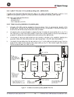
4.4.6.1  Notes concerning installation of a parallel system

1.

All inputs of the UPSs must be supplied from the same phase. This is to enable bypass operation of the

parallel system. All inputs must be individually protected by fuses in the installation. The values of these fuses

should correspond to the values mentioned in section 4.4 table 1.

2.

All outputs must be connected together, supplying the load. It is advised to install switches (S 1-4, fig. 17) in

the output wiring, in order to be able to isolate a unit from the remaining system for service and maintenance

purposes. It is advised to make a Neutral-to-Ground bounding in the output junction.

3.

The diameter of input and output cables must be according to the table in the installation drawings (see

appendix). Cables with different diameters can cause tripping fuses in the UPS and/or the installation.

4.

The length of all input cables from the input junction (Li, fig. 17) to the UPS inputs should be equal. The same

applies to the cables from the outputs to the output junction (Lo, fig. 17). The minimum length of the input as

well as the output cables is 3 meters / 10 feet.

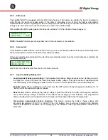
Figure 17.  Installation of parallel operating 

LanPro

®

-U


UPSs

F1

F2

F3

F4

LanPro

IN

OUT

INPUT JUNCTION

OUTPUT JUNCTION

TO LOAD

1-PHASE 3-WIRE INPUT

Li

Li

Li

Li

Lo

Lo

Lo

Lo

YELLOW NETWORK
CABLES AS DELIVERED
WITH THE UPS

Li / Lo: LENGTH OF I / O WIRING
- EQUAL FOR EACH UPS
- MINIMUM 3 METERS / 9.8 FEET

S 1 - 4

SWITCH ALLOWS
ISOLATION OF
A UNIT FROM
THE SYSTEM

F 1 - 4

DISTRIBUTION
FUSE OR BREAKER
VALUES ACCORDING
TO TABLE 1

LanPro

IN

OUT

LanPro

IN

OUT

LanPro

IN

OUT

RPA
CARD

BUS

TERMINATOR

S1

S2

S3

S4

BUS

TERMINATOR

RPA
CARD

RPA
CARD

RPA
CARD

MAKE
NEUTRAL-TO-GROUND
BOUNDING HERE

Содержание LanPro 11 U

Страница 1: ... SUPPLY LanPro 11 U 5 6 8 10 kVA Manufactured by GE Digital Energy General Electric Company Telephone 41 0 91 850 51 51 CH 6595 Riazzino Locarno Fax 41 0 91 850 51 44 Switzerland Website www gedigitalenergy com Technology for the Digital World ver 2 1 US LanPro U UPS ...

Страница 2: ...PS to ensure reliable performance for the user All units have passed GE DE s quality control standards and conform to the tolerances in the enclosed specifications About GE Digital Energy GE Digital Energy is a leading provider of mission critical power equipment and bridges the gap between the traditional electricity supply and the critical power requirements of today s businesses GE designs deve...

Страница 3: ...VA only 4 4 3 Available output voltages hardware modifications 4 4 3 1 Output voltage 208Vac 4 4 3 2 Output volatge 120Vac split phase 4 4 3 3 Output voltage 220 230 240Vac 4 4 3 4 Output voltage 120Vac single phase 4 4 4 Input output voltages Software modification 4 4 5 Installation of GE DE LanPro battery extension pack s 4 4 6 LanPro 11U series 2 3 4 parallel operating units additional info 4 4...

Страница 4: ...Card optional 6 4 SNMP Interface optional 7 OPTIONAL FEATURES 35 7 1 Extended Runtime 7 2 Plug in Cards 7 3 RPA Facility Redundant Parallel Architecture 7 4 PDM Power Distribution Module 7 5 Seismic Anchors 7 6 120Vac Single Phase Option Kit 8 MAINTENANCE 37 8 1 General 8 2 Cooling fan 8 3 Batteries 8 4 Safety 8 5 Storage 9 TROUBLESHOOTING 38 10 SPECIFICATIONS 39 APPENDIX INSTALLATION DRAWINGS ...

Страница 5: ...wire AC source equipped with an earth connection In this manual Earth is represented with two different symbols Field wiring equipment grounding terminal Grounding terminals Do not install the UPS in an excessively humid environment or near water Avoid getting liquids or any foreign object into the UPS The unit must be placed in a sufficiently ventilated area the ambient temperature should not exc...

Страница 6: ... The likelihood of such shock will be reduced if such grounds are removed during installation and maintenance More than ever before today s advanced electronic equipment with complex integrated circuits and other sensitive electronics needs a stable and continuous AC power supply to operate correctly While the power coming from the wall outlet is often unreliable a GE Digital Energy LanPro U UPS p...

Страница 7: ...extended utility failure the output converter will stop when the battery has been discharged At this point the UPS is no longer able to power the connected equipment When the utility is re established within tolerance the output converter will be supplied again by the input converter and the batteries will be recharged making them ready to support future power failures OUTPUT PERFECT UPS POWER OUT...

Страница 8: ... 3 5 Manual Bypass Switch Service switch The system can be bypassed manually using the manual bypass switch located at the rear panel It is a two position switch the normal position is 1 as in figures 2 4 Position 2 is the service position the load is directly connected to the utility input This way maintenance of the UPS e g battery replacement as in fig 5 is possible without interruption of the ...

Страница 9: ...f your utility supply is 120 208 230 240 Vac and 50 or 60 Hz from the factory the input and output of the UPS are set to 208 Vac 60 Hz Be sure that the UPS is wired for the present utility voltage This is indicated on the packaging of the UPS as well as at the I O terminals Overcurrent protection for the AC circuit is to be provided by others CAUTION To reduce risk of fire connect only to a circui...

Страница 10: ...ing minimum sizes INPUT WIRING Utility voltage UPS model 120V 208V 240V L5 11U 6 AWG 10 AWG 10 AWG L6 11U 4 AWG 8 AWG 10 AWG L8 11U N A 6 AWG 8 AWG L10 11U N A 4 AWG 6 AWG Table 2 Input wiring OUTPUT WIRING Output voltage UPS model 120V 208V 240V L5 11U 8 AWG 10 AWG 10 AWG L6 11U 8 AWG 10 AWG 10 AWG L8 11U 6 AWG 8 AWG 8 AWG L10 11U 4 AWG 8 AWG 8 AWG Table 3 Output wiring TIGHTENING TORQUE FORCE UP...

Страница 11: ...n emergency shutdown switch can be connected to connector J3 on the RS232 Contact Interface Card between pins 3 and 4 See section 6 2 for more information 7 For advanced communication possibilities the RS232 contact interface port 12a can be connected to a computer system See section 6 1 for more information 8 The middle option slot 13 allows easy installation of plug in cards SNMP Card or Relay C...

Страница 12: ... install the cover plate 11 and the conduit boxes 17 2x 6 An emergency shutdown switch can be connected to connector J3 on the RS232 Contact Interface Card between pins 3 and 4 See section 6 2 for more information 7 For advanced communication possibilities the RS232 contact interface port 12a can be connected to a computer system See section 6 1 for more information 8 The middle option slot 13 all...

Страница 13: ...2 Remove the yellow wire A from faston 61 park and place this wire on faston 74 connect 3 Connect the utility supply wires to terminals 6 L1 7 L2 and 8 equipment grounding conductor See figure 9 Ground connection is essential If a neutral wire is part of the site wiring provided we suggest to isolate this wire for future use or other applications 4 For the output voltage proceed with 4 4 3 1 2 3 4...

Страница 14: ...difications The off factory setting is 208 Vac a link is placed between terminals 2 and 3 An extra link was delivered with the unit in a plastic bag to enable other output voltages 5 6kVA models only The following voltages are available 120 208 220 230 240 Vac 4 4 3 1 Output voltage 208Vac This is the off factory setting There is a link between terminal 2 and 3 1 Connect the output wires to the te...

Страница 15: ...terminals 1 L1 and 2 N 120V and between the terminals 3 N and 4 L2 120V Connect the ground wire to terminal 5 Ground connection is essential Do not remove the link between terminals 2 and 3 See figure 13 3 Return to either 4 4 1 1 step 5 or 4 4 1 2 step 5 Figure 13 LanPro 5 6 8 10 11U 120 Vac split phase output connection 1 2 3 4 5 6 7 8 gnd L2 N gnd L1 120V 120V Figure 12 LanPro 5 6 8 10 11U Outp...

Страница 16: ... voltage 120Vac single phase 1 The factory setting of the output tap 208Vac has to be changed to 240Vac Follow the procedure as described in section 4 4 3 2 steps 1 1 and 1 2 2 Remove the link between terminals 2 and 3 Proceed as follows LanPro U 5 6kVA step 3 6 LanPro U 8 10kVA step 7 10 For LanPro U 5 6kVA 3 Place this link between terminal 1 and 2 4 Place the extra link delivered with the unit ...

Страница 17: ... through the several setup screens Enter reset confirms the screen choice Go to the setup screen INPUT VOLTAGE 4 Here you can change the input voltage to 240 Volt The value of the input voltage blinks Scroll through its settings by using the push buttons up and down the new setting is confirmed by pressing enter reset 5 Go to the setup screen OUTPUT VOLTAGE 6 Here you can change the output voltage...

Страница 18: ...can install a second third etc pack 7Ah battery packs cannot be connected in parallel NOTE A maximum of two GE Digital Energy 14Ah battery cabinets can be connected without additional fusing Every two additional GE Digital Energy 14Ah battery cabinets must be connected over a 60Amp fuse rated for 300Vdc NOTE Third party battery cabinets must be connected over a 60Amp fuse rated for 300Vdc using th...

Страница 19: ...to isolate a unit from the remaining system for service and maintenance purposes It is advised to make a Neutral to Ground bounding in the output junction 3 The diameter of input and output cables must be according to the table in the installation drawings see appendix Cables with different diameters can cause tripping fuses in the UPS and or the installation 4 The length of all input cables from ...

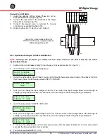
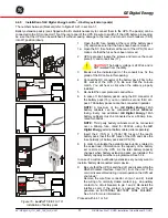
Страница 20: ...its have not been interconnected yet be sure that utility power is connected to the UPS start each unit individually see 5 2 check change the parameters and switch the unit off again 7 Interconnect the RPA cards of the units using the network cable that came with the UPS See figure 17 dotted line Only install the cables that were delivered with the UPSs Of the first and the last UPS in the system ...

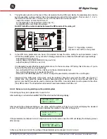
Страница 21: ...the UPSs to bypass operation using the manual bypass switch switch is turned into position 2 then all UPSs in the parallel system have to be switched to bypass operation in order to prevent damage Maintenance To isolate a unit from the redundant system 1 Switch off the UPS which has to be isolated 2 Remove the installation fuse from the input of that UPS F1 4 in figure 17 3 Separate the output of ...

Страница 22: ...mation 7 Switch UPS on off turns on off the complete UPS including the automatic bypass 8 Circuit breaker Utility on off protection fuse for utility input and battery charger 9 Circuit breaker Bypass on off fuse to protect the system in case of severe overload or short circuit in the UPS load 10 Manual Bypass Switch 1 Load on UPS 2 Load on utility WARNING In position 2 if the input line is energiz...

Страница 23: ...minals L N and GND 17 Conduit box 18 Cable inlet Rear panel of optional battery extension pack 15 DC socket 14Ah only 15a DC connector 16 Battery fuse holder s 7Ah 2 fuses 14Ah 4 fuses 19 Gland to fasten cable in conduit box of UPS 17 18 11b 15a 16 15 14Ah 19 Figure 21 Rear panel battery extension pack optional Figure 20 Rear panel of the step up transformer ...

Страница 24: ...osition on up The green LED operation front panel 5 will illuminate After switching on the UPS performs a self test and the display front panel 1 will show After completion of the self test the output voltage of the UPS is available and the unit is ready for use The display will show the default screen model and actual load values are examples In case of a system failure the self test results in a...

Страница 25: ...nformation see 6 1 The menus on the display can be divided into 5 groups 1 standard screen 2 information menu 5 3 1 3 status and alarm menu 5 3 2 4 service menu 5 3 3 5 set up menu 5 3 4 The standard menu shows UPS model and actual load 5 3 1 Information Menu When the default screen is displayed the first information screen can be entered by depressing the up key front panel 4 Using the up and dow...

Страница 26: ...anteed This text alternates with the following screen showing the actual load as of the nominal UPS rating These messages are displayed if the load is 100 If the load exceeds 150 the UPS will immediately switch to bypass assuming that the conditions for a transfer to bypass are fulfilled If an overload condition between 100 150 persists the UPS can eventually also switch to bypass operation due to...

Страница 27: ...e to power the connected equipment The static bypass circuit breaker rear panel 9 is in off down position no bypass voltage available Utility voltage is available If not manually operated this may have been caused by an overload situation The utility circuit breaker rear panel 8 is in the off down position no line voltage available bypass voltage is available If not manually operated this may have...

Страница 28: ... no input voltage and load 2 If the input voltage is restored the output will be available again See also section 5 5 1 The wire on connector J3 pin 3 4 rear panel plug in card 12 is interrupted The output is no longer available To restart the unit restore the connection and turn the on off switch rear panel 7 off and on again 5 3 3 Service Menu When the default screen is displayed you can enter t...

Страница 29: ... is not within limits the lower line will show the text UNAVAILABLE Service set up information whether the bypass is enabled default or disabled If disabled UPS will NOT go to bypass For disabling the bypass refer to the setup menu 5 3 4 Service set up information about the total battery capacity Information about the actual battery charge condition For changing the programmed battery capacity ref...

Страница 30: ...output frequency Range 50 60 Hz CAUTION Changing of the output frequency can cause severe damage of equipment connected to the UPS Be sure that the new frequency is suitable for the connected equipment The frequency tracking range in which the output converter frequency will follow the bypass frequency Range 2 4 6 If the bypass frequency is beyond the setting the output converter will return to th...

Страница 31: ...ery tests to ensure that the batteries and the wiring are able to support power failures The tests do not cause any interruption in the functioning of the unit Manual test A manual battery test can be activated either through an interface kit via the RS232 or SNMP Interface Port please refer to the manual of your interface package or via the front panel see below 5 4 2 Quick Battery Test From the ...

Страница 32: ...e than 30 of nominal load The batteries should be fully charged 100 on screen There are no alarms at the time the test is started Procedure From the standard menu first enter the service menu press the down and enter reset keys simultaneously for 2 seconds Subsequently press the down key until the following screen appears Press the keys down 2 enter reset 3 simultaneously for at least 1 second The...

Страница 33: ...put voltage is no longer available LED operation blinks green and the LCD screen shows the time left until restart If a utility failure occurs during the sleep period and the battery voltage eventually drops below 200Vdc the UPS will automatically switch off in order to save battery power When the main returns the UPS will start up automatically The programmed sleep time however is lost The sleep ...

Страница 34: ...he display will show After Enter the unit will restart See also 5 3 3 service screens 5 5 7 Superior Battery Management Load dependent battery end voltage The allowable final battery voltage depends on the discharge current the higher the current the lower the end of discharge battery voltage This gives maximum capacity without over discharging Over discharging results in failure to recover normal...

Страница 35: ... 5 Common 6 Bypass active 7 Plug Play RTS 8 Utility failure 9 General alarm contact interface Max 48V 30mA 6 2 Emergency shutdown The emergency shutdown connector is located on the RS232 contact interface card 12 Be sure that the UPS is switched off and remove the card from the unit Remove the wire from connector J3 pin 3 and 4 Install the wiring of a normally closed contact to connector J3 pin 3 ...

Страница 36: ...lot rear panel 13 allows easy installation of a relay or SNMP plug in card See sections 6 3 and 6 4 for more information 7 3 RPA Facility Redundant Parallel Architecture Nowadays there are many mission critical applications that need a fault tolerant 100 reliable availability of utility power By adding the RPA facility to the LanPro U rear panel 14 highest standards for reliability can be met The ...

Страница 37: ...S Only qualified personnel is allowed to install the PDM For more information please refer to the user manual that comes with the Power Distribution Module A Connector Nema L14 30R 1 B TCBs 8 C Connector Nema L6 30R 2 D Connector Nema L5 20R 4 7 5 Seismic anchors Seismic anchors can be ordered separately contact your local dealer 7 6 120Vac Single Phase Option Kit This kit is required in case of 1...

Страница 38: ...uding battery replacement should be performed by qualified service personnel For authorized service personnel only Never short the battery terminals Shorting may cause the battery to burn Avoid charging in a sealed container Proper disposal of batteries is required refer to your local codes for disposal requirements Never dispose of batteries in a fire they may explode Never disassemble or reassem...

Страница 39: ...detected on the output terminals Please contact your dealer The internal battery fuse is defective Please contact your dealer The battery extension circuit breaker is in the off position Please switch it to the on position Malfunction of the battery charger Please contact your dealer Malfunction of the input circuit voltage delivered is too high Please contact your dealer The temperature of one of...

Страница 40: ...e out 380 V BATTERY CHARGER Characteristic U I characteristic constant current charging until boost float voltage then constant voltage charging and boost charge mode for fast recharging of batteries DC input voltage range 350 450 V DC output voltage at 20 C float 273 V boost 295 V Output current limit Adc 2 0 2 0 3 0 3 0 OUTPUT CONVERTER Output power at pf 0 8 VA 5000 6000 8000 10000 Semiconducto...

Страница 41: ...ating conditions Battery discharging self discharge current 0 35 mA discharge end voltage of the battery depending on the actual load 10 5Vdc 0 2 CA till 9 0 Vdc 2 CA When the UPS is in sleeping mode the inverter will be switched off battery charger and rectifier are in operation Runtime in minutes VA Watts 1000 800 60 60 120 120 2000 1600 40 40 60 60 3000 2400 18 18 40 40 5000 4000 10 10 22 22 60...

Страница 42: ...s hxwxd inch 26 8x12 3x28 7 26 8x12 3x28 7 26 8x12 3x28 7 26 8x12 3x28 7 height with castors Weight with batteries Kg 134 kg 134 kg 175 kg 186 kg Weight with batteries Lbs 295 Lbs 295 Lbs 386 Lbs 410 Lbs GENERAL DESIGN CRITERIA Mechanical IP20 Humidity 95 non condensing Safety UL 1778 2001 C UL EN 50091 1 1 1999 EN 60950 IEC 950 2001 Surge capability 6kV 1 2 50µs 3kA 8 20µs EMC FCC part 15 class A...

Страница 43: ... GE DE LanPro 11U UPS Installation User Manual 2 1 US GE Digital Energy g Dimensions conduit box Front W D H W 155mm 6 1 Inch D 300mm 11 8 Inch H 275mm 10 8 Inch VSD2 h x w x d 680 x 310 x 710 mm 26 8 x 12 2 x 28 Inch Center of gravity ...

Страница 44: ...2 3 28 7 386 660 14 104 95 N A 6 14 8 10 6 14 8 10 8 10 10 11U 1090 3719 556 1896 26 8 12 3 28 7 410 660 14 104 95 N A 4 22 6 14 4 22 8 10 8 10 5 11U 120 V 641 2187 425 1451 39 2 12 3 28 7 386 660 14 104 95 6 14 N A N A 8 10 10 6 10 6 6 11U 120 V 744 2539 601 2051 39 2 12 3 28 7 386 660 14 104 95 1000 derating 12 5 per 1000 4 22 N A N A 8 10 10 6 10 6 Model Minimum free space required Inches front...

Страница 45: ... EARTH CONNECTION IS ESSENTIAL UPS UTILITY STATIC BYPASS ON OFF 1 2 BATTERY DISCONNECTED 3 4 EMERGENCY SHUTDOWN RS232 CONTACT SEE BELOW SNMP CARD OR RELAY CARD RPA CARD PARALLEL OPERATION 1 BATTERY LOW 6 BYPASS ACTIVE 2 SERIAL DATA OUT 7 PLUG PLAY RTS 3 SERIAL DATA IN UPS SHUTDOWN 8 MAINS FAILURE 4 NOT USED 9 GENERAL ALARM 5 COMMON x y 4 x M8 w CASTORS h d CONDUIT BOX CABLE ENTRY A B POSITION A FI...

Страница 46: ...ECTED 3 4 EMERGENCY SHUTDOWN 1 BATTERY LOW 6 BYPASS ACTIVE 2 SERIAL DATA OUT 7 PLUG PLAY RTS 3 SERIAL DATA IN UPS SHUTDOWN 8 MAINS FAILURE 4 NOT USED 9 GENERAL ALARM 5 COMMON INPUT OUTPUT TERMINALS BATTERY FUSES CONTROLS CIRCUIT BREAKERS BATTERY PACK CONNECTOR OPTION SLOTS RS232 CONTACT INTERFACE SUB D PINNING EARTH CONNECTION IS ESSENTIAL INPUT TERMINALS CONDUIT BOX CABLE ENTRY d h w z y POSITION...

Отзывы: