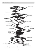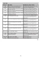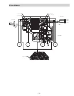
– 33 –
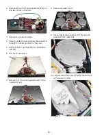
Remove ten 1/4 in. hex head screws from the
UHFHVVHGDUHDVDQGOLIWRȺWKHHOHPHQWSODWH
The induction cooling fan motor must be transferred
to the new module.
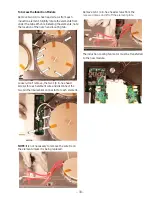
To Access the Induction Module
Remove two 1/4 in. hex head screws from each
induction element. Slightly rotate the elements from
under the tabs. When reinstalling the elements, note
the location of the notch and locating tab.
Loosen, don’t remove, the two 1/4 in. hex head
screws for each element wire and disconnect the
two pin thermal sensor connector for each element.
NOTE: It is not necessary to remove the wire tie on
the element unless it is being replaced.
Содержание JP3030*J series
Страница 11: ...11 To Access the Relay Board 1 5HPRYH YH LQ KH KHDG VFUHZV IURP WKH UHOD ERDUG FRYHU Relay Board...
Страница 12: ...12 Wiring Diagram Electronic Control...
Страница 13: ...13 Schematic Electronic Control...
Страница 17: ...17 13 Large elements also have a bracket that secures with one 1 4 in screw...
Страница 42: ...42 Q QLWH 6ZLWFK 6FKHPDWLF...
Страница 43: ...43 Q QLWH 6ZLWFK Wiring Diagram...
Страница 44: ...44 Accessories Parts Griddle JXGRIDL1 Sous Vide Kit JXSOUSV1 Stainless Steel Cleaner and Polisher PM10X311...

