– 32 –
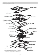
Induction Component Access
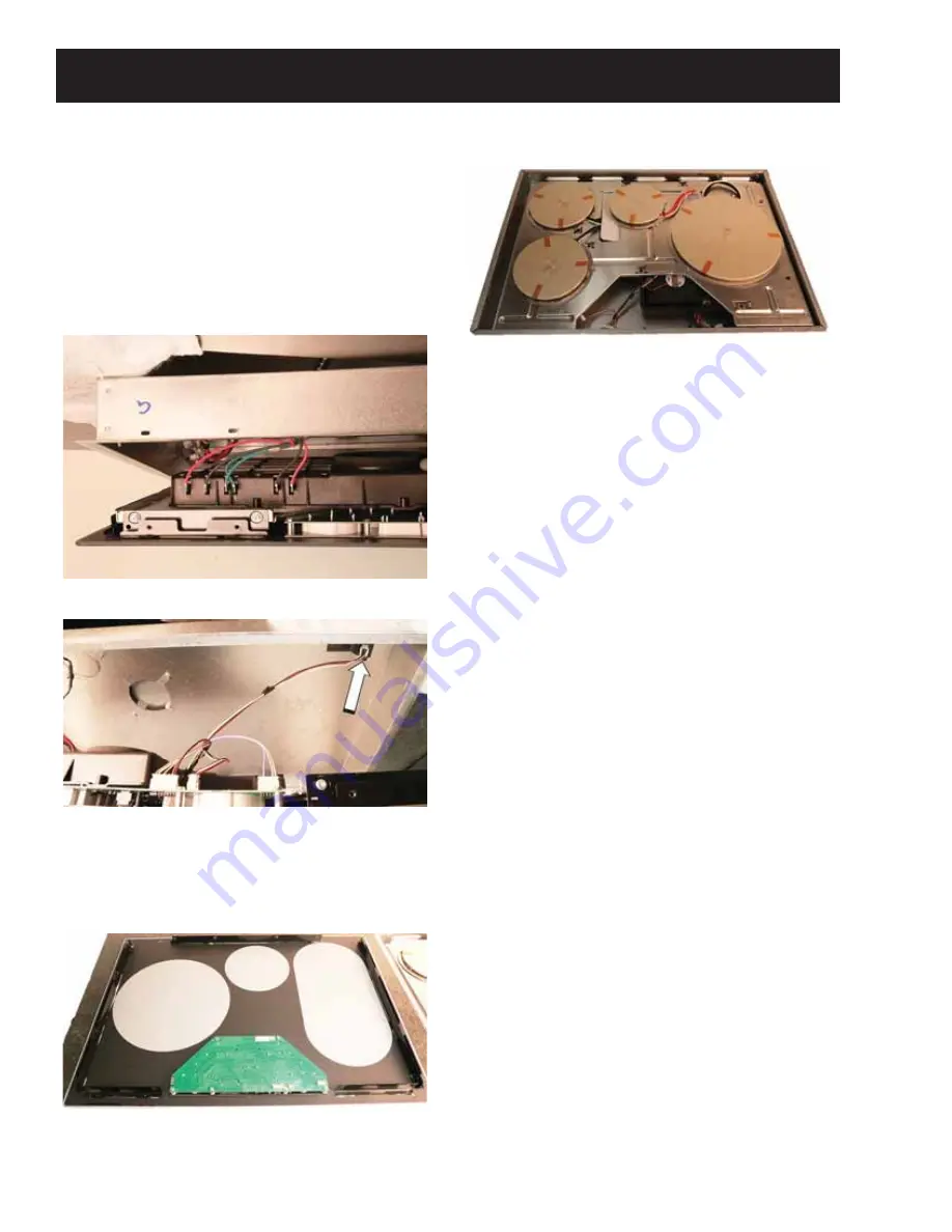
1. Disconnect power to the cooktop.
2. Carefully remove the cooktop from the
installation and lay glass side down on a
protected surface.
3. Remove T20 screws from the perimeter.
4. Raise the bottom cover about six inches and
disconnect the two L1, L2 and ground wires
from the module.
5. Disconnect the RJ45 harness connector.
6. Remove the bottom cover and set back into
installation opening.
7. Remove 1/4 in. hex head screws from the
perimeter cooktop frame.
8. Set the induction module back into the bottom
cover.
Содержание JP3030*J series
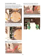
Страница 11: ...11 To Access the Relay Board 1 5HPRYH YH LQ KH KHDG VFUHZV IURP WKH UHOD ERDUG FRYHU Relay Board...
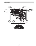
Страница 12: ...12 Wiring Diagram Electronic Control...
Страница 13: ...13 Schematic Electronic Control...
Страница 17: ...17 13 Large elements also have a bracket that secures with one 1 4 in screw...
Страница 42: ...42 Q QLWH 6ZLWFK 6FKHPDWLF...
Страница 43: ...43 Q QLWH 6ZLWFK Wiring Diagram...
Страница 44: ...44 Accessories Parts Griddle JXGRIDL1 Sous Vide Kit JXSOUSV1 Stainless Steel Cleaner and Polisher PM10X311...

