


Troubleshooting and System Messages
Invenia ABUS 2.0 – System Setup and Basic Service Manual
7-33
4700-0043-00 Rev. 4
EMI prevention/
abatement
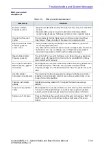
Table 7-4: EMI prevention/abatement
EMI RULE
DETAILS
Be aware of Radio
Frequency sources
• Keep the Invenia ABUS 2.0 at least 5 meters (15 feet) away from other EMI
sources.
• Special shielding may be required to eliminate interference problems
caused by high frequency, high powered radio or video broadcast signals.
Ground the Ultrasound
system
Poor grounding is the most likely reason an Ultrasound system will have
noisy images. Check grounding of the power cord and power outlet.
Replace all screws, Radio
Frequency gaskets,
covers, cores
• After you finish repairing or updating the Invenia ABUS 2.0, replace all
covers and tighten all screws.
• Any cable with an external connection requires a magnet wrap at each end.
• Install all covers. Loose or missing covers or Radio Frequency gaskets
allow radio frequencies to interfere with the ultrasound signals.
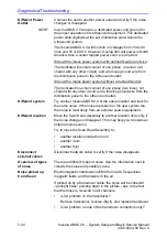
Replace broken Radio
Frequency gaskets
If more than 20% or a pair of the fingers on an Radio Frequency gasket are
broken, replace the gasket. Do not turn on the Invenia ABUS 2.0 until any
loose metallic part is removed.
Do not place labels where
Radio Frequency gaskets
touch metal
Where applicable, never place a label where Radio Frequency gaskets meet
the Ultrasound system. Otherwise, the gap created will permit Radio
Frequency leakage. Or, if a label has been found in such a position, move the
label.
Use GE specified
harnesses and peripherals
The interconnect cables are grounded and require ferrite beads and other
shielding. Also, cable length, material, and routing are all important; do not
change from what is specified.
Take care with cellular
phones
Cellular phones may transmit a 5 V/m signal; that could cause image
artifacts.
Properly route peripheral
cables
Where applicable, do not allow cables to lie across the top of the Card Rack
or hang out of the peripheral bays. Loop the excess length for peripheral
cables inside the peripheral bays. Attach the monitor cables to the frame.
System won’t shut down
Press and hold down the power button until the system shuts down. ONLY do
this if the system does not shut down normally (light press of the power
button).
Содержание H5018SC
Страница 5: ...Invenia ABUS 2 0 System Setup and Basic Service Manual i 3 4700 0043 00 Rev 4 ...
Страница 6: ...i 4 Invenia ABUS 2 0 System Setup and Basic Service Manual 4700 0043 00 Rev 4 ...
Страница 7: ...Invenia ABUS 2 0 System Setup and Basic Service Manual i 5 4700 0043 00 Rev 4 ...
Страница 8: ...i 6 Invenia ABUS 2 0 System Setup and Basic Service Manual 4700 0043 00 Rev 4 ...
Страница 9: ...Invenia ABUS 2 0 System Setup and Basic Service Manual i 7 4700 0043 00 Rev 4 ...
Страница 10: ...i 8 Invenia ABUS 2 0 System Setup and Basic Service Manual 4700 0043 00 Rev 4 ...
Страница 11: ...Invenia ABUS 2 0 System Setup and Basic Service Manual i 9 4700 0043 00 Rev 4 ...
Страница 12: ...i 10 Invenia ABUS 2 0 System Setup and Basic Service Manual 4700 0043 00 Rev 4 ...
Страница 13: ...Invenia ABUS 2 0 System Setup and Basic Service Manual i 11 4700 0043 00 Rev 4 ...
Страница 14: ...i 12 Invenia ABUS 2 0 System Setup and Basic Service Manual 4700 0043 00 Rev 4 ...
Страница 15: ...Invenia ABUS 2 0 System Setup and Basic Service Manual i 13 4700 0043 00 Rev 4 ...
Страница 16: ...i 14 Invenia ABUS 2 0 System Setup and Basic Service Manual 4700 0043 00 Rev 4 ...
Страница 26: ...i 24 Invenia ABUS 2 0 System Setup and Basic Service Manual 4700 0043 00 Rev 4 ...
Страница 74: ...Site Preparations 2 20 Invenia ABUS 2 0 System Setup and Basic Service Manual 4700 0043 00 Rev 4 ...
Страница 162: ...Functional Checks 4 16 Invenia ABUS 2 0 System Setup and Basic Service Manual 4700 0043 00 Rev 4 ...
Страница 260: ...Replacement Procedures 8 16 Invenia ABUS 2 0 System Setup and Basic Service Manual 4700 0043 00 Rev 4 ...
Страница 277: ......
Страница 278: ...1 2 Invenia ABUS 2 0 System Setup and Basic Service Manual 4700 0043 00 Rev 4 ...


