General theory of operation
Invenia ABUS 2.0 – System Setup and Basic Service Manual
5-19
4700-0043-00 Rev. 4
Scan Head
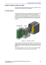
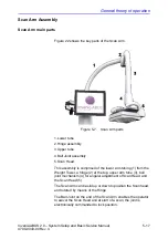
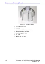
Figure 5-7 identifies the parts of the Scan Head.
The Scan Head physically supports the Ultrasound Transducer,
provides an operator with means for adjusting Transducer
position, and has operator controls.
The Transducer is held in the Scan Head's center compartment
area. The ABUS 2.0 uses the C15-6XW Reverse Curve
Transducer. Each Transducer is serial numbered and its ID can
be read from system diagnostics.
The head has two handles for position adjustment, and each
handle has operator control pushbuttons.
The Scan Head has at its bottom a disposable
magnetically-attached frame holding a fine-mesh Single-Use
Stabilizing Membrane. During a scan, the head slides the
Transducer over the membrane, which the system presses
against the surface of the breast with adjustable compression.
To prepare for a scan, the operator applies lubricating medium
(lotion or gel) to the breast. This acoustically couples the tissue
through the mesh to the Transducer and lubricates the
Transducer's motion across the surface. After a scan, the
operator must discard the membrane assembly and carefully
clean the lotion from the Transducer. Note that accuracy of a
scan requires a generally even layer of lotion across the breast.
Uneven application such as missing patches can cause image
artifacts.
Inside the head's controls compartment is a control electronics
board and the stepping motor that moves the Transducer
horizontally for a scan. Commands from the buttons are relayed
by USB from the electronics board back down to the Ultrasound
Box and from there, also by USB, to the PC Box.
The Scan Head has two LED lighting strips illuminating the
inside area around the Transducer.
Содержание H5018SC
Страница 5: ...Invenia ABUS 2 0 System Setup and Basic Service Manual i 3 4700 0043 00 Rev 4 ...
Страница 6: ...i 4 Invenia ABUS 2 0 System Setup and Basic Service Manual 4700 0043 00 Rev 4 ...
Страница 7: ...Invenia ABUS 2 0 System Setup and Basic Service Manual i 5 4700 0043 00 Rev 4 ...
Страница 8: ...i 6 Invenia ABUS 2 0 System Setup and Basic Service Manual 4700 0043 00 Rev 4 ...
Страница 9: ...Invenia ABUS 2 0 System Setup and Basic Service Manual i 7 4700 0043 00 Rev 4 ...
Страница 10: ...i 8 Invenia ABUS 2 0 System Setup and Basic Service Manual 4700 0043 00 Rev 4 ...
Страница 11: ...Invenia ABUS 2 0 System Setup and Basic Service Manual i 9 4700 0043 00 Rev 4 ...
Страница 12: ...i 10 Invenia ABUS 2 0 System Setup and Basic Service Manual 4700 0043 00 Rev 4 ...
Страница 13: ...Invenia ABUS 2 0 System Setup and Basic Service Manual i 11 4700 0043 00 Rev 4 ...
Страница 14: ...i 12 Invenia ABUS 2 0 System Setup and Basic Service Manual 4700 0043 00 Rev 4 ...
Страница 15: ...Invenia ABUS 2 0 System Setup and Basic Service Manual i 13 4700 0043 00 Rev 4 ...
Страница 16: ...i 14 Invenia ABUS 2 0 System Setup and Basic Service Manual 4700 0043 00 Rev 4 ...
Страница 26: ...i 24 Invenia ABUS 2 0 System Setup and Basic Service Manual 4700 0043 00 Rev 4 ...
Страница 74: ...Site Preparations 2 20 Invenia ABUS 2 0 System Setup and Basic Service Manual 4700 0043 00 Rev 4 ...
Страница 162: ...Functional Checks 4 16 Invenia ABUS 2 0 System Setup and Basic Service Manual 4700 0043 00 Rev 4 ...
Страница 260: ...Replacement Procedures 8 16 Invenia ABUS 2 0 System Setup and Basic Service Manual 4700 0043 00 Rev 4 ...
Страница 277: ......
Страница 278: ...1 2 Invenia ABUS 2 0 System Setup and Basic Service Manual 4700 0043 00 Rev 4 ...

