


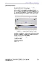
Components and Functions (Theory)
5-6
Invenia ABUS 2.0 – System Setup and Basic Service Manual
4700-0043-00 Rev. 4
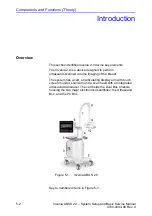
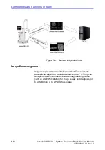
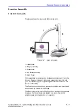
touchscreen monitor assembly, and conveying cabling to
Scan Head and Display)
•
Scan Arm from the Weight Tower, providing support for, and
adjustment of, Scan Head; includes electronically controlled
lockable ball joint
•
Scan Head Assembly including Scan Head with Transducer,
and operator control buttons
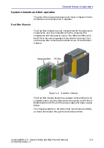
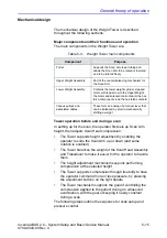
Electrical, electronic, and computer main elements
These are contained inside the Dual Box Chassis. The two
boxes are:
•
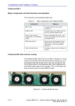
Ultrasound Box containing the cMST board for ultrasound
processing, MFEPS power board, and MPSB Relay Board
•
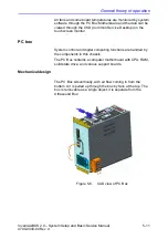
PC Box containing the computer motherboard and
associated components such as GPU and SSD, and the
ACDC power supply box
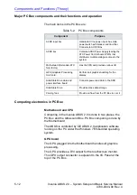
Controls, indicators, and display
The system controls and their locations are:
Control
Location
Endpoint
ON/OFF Power Switch on
chassis
lower
This connects to the PC motherboard
Display (Touch Screen)
on ergo display
arm
This connects to the GPU card via DVI cable, and
via USB to Motherboard
Scan Head pushbuttons
on Scan Head
arms
These are sensed by the Scan control PWA within
Scan Head. The board reports their state to the
Motherboard via USB
Power Check OK LED
on top of PC Box
Driven from ACDC box; lights when all outputs from
ACDC box are operational
Содержание H5018SC
Страница 5: ...Invenia ABUS 2 0 System Setup and Basic Service Manual i 3 4700 0043 00 Rev 4 ...
Страница 6: ...i 4 Invenia ABUS 2 0 System Setup and Basic Service Manual 4700 0043 00 Rev 4 ...
Страница 7: ...Invenia ABUS 2 0 System Setup and Basic Service Manual i 5 4700 0043 00 Rev 4 ...
Страница 8: ...i 6 Invenia ABUS 2 0 System Setup and Basic Service Manual 4700 0043 00 Rev 4 ...
Страница 9: ...Invenia ABUS 2 0 System Setup and Basic Service Manual i 7 4700 0043 00 Rev 4 ...
Страница 10: ...i 8 Invenia ABUS 2 0 System Setup and Basic Service Manual 4700 0043 00 Rev 4 ...
Страница 11: ...Invenia ABUS 2 0 System Setup and Basic Service Manual i 9 4700 0043 00 Rev 4 ...
Страница 12: ...i 10 Invenia ABUS 2 0 System Setup and Basic Service Manual 4700 0043 00 Rev 4 ...
Страница 13: ...Invenia ABUS 2 0 System Setup and Basic Service Manual i 11 4700 0043 00 Rev 4 ...
Страница 14: ...i 12 Invenia ABUS 2 0 System Setup and Basic Service Manual 4700 0043 00 Rev 4 ...
Страница 15: ...Invenia ABUS 2 0 System Setup and Basic Service Manual i 13 4700 0043 00 Rev 4 ...
Страница 16: ...i 14 Invenia ABUS 2 0 System Setup and Basic Service Manual 4700 0043 00 Rev 4 ...
Страница 26: ...i 24 Invenia ABUS 2 0 System Setup and Basic Service Manual 4700 0043 00 Rev 4 ...
Страница 74: ...Site Preparations 2 20 Invenia ABUS 2 0 System Setup and Basic Service Manual 4700 0043 00 Rev 4 ...
Страница 162: ...Functional Checks 4 16 Invenia ABUS 2 0 System Setup and Basic Service Manual 4700 0043 00 Rev 4 ...
Страница 260: ...Replacement Procedures 8 16 Invenia ABUS 2 0 System Setup and Basic Service Manual 4700 0043 00 Rev 4 ...
Страница 277: ......
Страница 278: ...1 2 Invenia ABUS 2 0 System Setup and Basic Service Manual 4700 0043 00 Rev 4 ...


