background image

15

GEAppliances.com

1.

To enter diagnostics, press and hold
the

MODE

button for 3 seconds until 

the Low Salt Alarm screen shows.

2.

Press the 

MODE

button 2 times to 

advance through Low Salt Alarm 
and Salt Efficiency options. See

Programming the Control

for details 

on these two options.

3. OPERATION OF DIAGNOSTICS

Valve Position – 

Press the 

RECHARGE

button to

initiate a recharge cycle. Press again to manually index
valve to next position. See 

Service: Manually Advance

Recharge Check

for details.

0 – Service
1 – Fill
2 – Brine
3 – Backwash
4 – Fast Rinse

Motor Operation – 

Two dashes will circulate around 

when motor should be running.

Position Switch Operation – 

– Closed – valve rotating to next position

– Open – valve in position, service, fill, brine, etc.

Water Meter – 

Indicates whether water is flowing 

through valve.

– 000 indicates no water is flowing through the valve

– Open nearby soft water faucet

– 000 to 199(continual) shows water is flowing.

Display repeats for each gallon of water passing through the
meter. Control will beep at every gallon. (1 gallon= 3.78 litres)

– If there is no reading in the display, with faucet

open, check the sensor. Pull the sensor from the
valve outlet port, and pass a small magnet in front 
of the sensor. Counter should index in the display. 
If counter does not index, check to make sure
harness is connected to board properly. If there is 
a reading in the display, there may be a problem
associated with the turbine. Turn off water supply,
close the by-pass valve, and disconnect by-pass valve
from valve body. Check turbine for binding or
restriction due to debris. If this does not correct 
the problem, the Timer, Sensor, or Turbine may
require replacement.

4.

Historical data about the softener is available.

Press and hold the UP 

button to display the number

of days this control has had electrical power applied.

Press and hold the DOWN 

button to display the

number of recharges initiated by this control since the
model code number was entered.

5.

Press the 

MODE

button to return to normal operation 

and display.

Service: Set Model (F) Code

1.

To change or check model code, first press and hold the

MODE

button for 3 seconds until the Low Salt Alarm

screen shows.

2.

Press and hold the 

MODE

button again 

for 3 seconds. A display with 

at 

the top will appear.

3.

Press the UP 

or DOWN 

buttons

to select the correct model code.

 F18 = GXOF18G

4.

Press the 

MODE

button one time to return to normal

operation and display. If the model code was changed:

the display will go blank momentarily, then display the
model code entered.

the display will then return to the set present time
display, and the blue indicator light will flash. The
control will have to be reprogrammed. See 

Programming

the Control

.

NOTE:

If the control is left in any of the above diagnostic

displays, or a flashing display when setting time, hardness,
etc., it will revert back to the normal display in 4 minutes.

Service: Manually Initiated Electronics Diagnostics

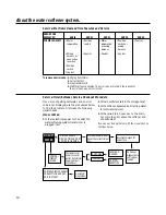
SALT

LEVEL

SALT

LEVEL

SALT

LEVEL

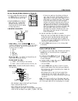
Water meter

Valve
position

Position
switch

Motor

Motor

Turbine

Turbine support
and shaft

Sensor
housing

Position
switch

Valve
outlet

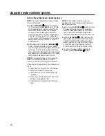
SALT

LEVEL

H45

Содержание GXOF18G

Страница 1: ...Tips 18 20 Consumer Support Parts list 87 www GEAppliances com 30500 General GXOF18G Euro Version 10 04 Write the model and serial numbers here Model ____________________________ Serial ____________________________ To find these numbers lift the cover and look on the rim below the control panel GXOF18G Owner s Manual Installation Instructions System tested and certified by NSF International agains...

Страница 2: ...NS PROPER INSTALLATION Install or store where it will not be exposed to temperatures below freezing or exposed to any type of weather Water freezing in the system will break it Do not attempt to treat water over 37 C Do not install in direct sunlight Excessive sun or heat may cause distortion or other damage to non metallic parts Properly ground to conform with all governing codes and ordinances U...

Страница 3: ...er connections as required by state and federal codes Connect the softener to the main water supply pipe before or ahead of the water heater DO NOT RUN HOT WATER THROUGH THE SOFTENER Temperature of water passing through the softener must be less than 49 C Use care when handling the softener Do not turn upside down drop drag or set on sharp protrusions Maximum allowable inlet water pressure is 8 6 ...

Страница 4: ... m power cable If the outlet is remote up to 30 meters use 0 8 mm2 wire to connect Be sure the electric outlet and transformer are in an inside location to protect from wet weather Be sure the outlet is unswitched to prevent accidental shutoff If installing in an outside location you must take the steps necessary to assure the softener installation plumbing wiring etc are as well protected from th...

Страница 5: ...ll out for soft water service Push in for bypass Nut 2 not supplied Copper tube 3 4 2 not supplied Washer 2 not supplied Installation adapter 2 see above INLET Union not supplied 2 Optional 3 Valve Bypass Installation Illustration Adapters for this installation are not supplied with the softener Fig 1 CROSSOVER Use if water supply flows from the left Include single or 3 valve bypass Hard water Fro...

Страница 6: ...shown in Fig 1 page 5 If house water flows up from the floor level turn the bypass valve upside down as shown in Fig 3C If making a soldered copper installation do all sweat soldering before connecting pipes to the bypass valve Torch heat will damage plastic parts When turning threaded pipe fittings onto plastic fittings use care not to cross thread Use pipe joint compound on all external pipe threads...

Страница 7: ...VATE this hose higher than the elbow on the brine tank IMPORTANT DO NOT TEE OVERFLOW HOSE TO VALVE DRAIN HOSE NOTE This drain is for safety only If the cabinet brine tank should over fill with water the excess is carried to the drain 6 INSTALL GROUNDING CLAMP not included DANGER Failure to properly attach ground clamp could result in electrical shock If plumbing is metal to maintain electrical grou...

Страница 8: ...rains per gallon press MODE to accept NOTE If there is clear water iron in your water supply you will need to increase the hardness setting by 5 for each 1 ppm of clear water iron in your water supply You can get the grains per gallon gpg hardness of your water supply from a water analysis laboratory If you are on a municipal supply call your local water department To calculate the gpg hardness fr...

Страница 9: ...NALS If there is an error code detected the blue indicator light will flash 4 times every second the display will flash Err and the alarm will beep every 30 seconds from 8 00 AM to 8 00 PM to signal that the softener requires service The alarm can be turned off by pressing any button but the blue indicator light and display will continue to flash See page 14 for information to assist in troubleshooti...

Страница 10: ...diate recharge RECHARGE begins to flash in the display The bleach will be drawn through the water softener and out the drain This process takes approximately 2 hours 4 If after sanitization water from the house faucet tastes salty or has a slight color this is a preservative from the resin tank Turn on the cold soft water faucets and drain for a few minutes or until clear NOTE When the above sanit...

Страница 11: ...heater will fill with the hard water Automatic Hard Water Bypass During Recharge Fill Salt dissolved in water is called brine Brine is needed to clean the hard minerals from resin beads To make the brine water flows into the salt storage area during the fill stage Brining During brining brine travels from the salt storage area into the resin tank Brine is the cleaning agent needed to remove hard m...

Страница 12: ...he resin tank during recharge If it becomes plugged with sand dirt etc the water softening system will not work and you will get hard water To get to the nozzle and venturi remove the water softening system top cover Be sure the water softening system is in service cycle no water pressure at nozzle and venturi Then while holding the nozzle and venturi housing with one hand remove the cap Lift out ...

Страница 13: ...ystem begins an immediate recharge and when over in about two hours you will have a new supply of soft water Once started you cannot cancel this recharge Feature Optional Recharge Controls Feature Memory If electrical power to the water softening system is interrupted the control display is blank and the blue indicator light is off but the control keeps correct time for about 6 hours When power is...

Страница 14: ... Time Features and Service If you are not getting soft water and an error code is not displayed use the procedures below to find the problem First make the following visual checks VISUAL CHECKS 1 Is there electrical power to the outlet the water softening system transformer is plugged into 2 Is there sufficient salt in the storage tank 3 Is the softener bypass valve directing water for soft water ...

Страница 15: ...e the by pass valve and disconnect by pass valve from valve body Check turbine for binding or restriction due to debris If this does not correct the problem the Timer Sensor or Turbine may require replacement 4 Historical data about the softener is available Press and hold the UP button to display the number of days this control has had electrical power applied Press and hold the DOWN button to di...

Страница 16: ...m contacting salt See Care and cleaning of the water softening system section If the water softening system does not draw brine check nozzle and or venturi dirty or defective defective nozzle and venturi seal nozzle and venturi not seated properly on gasket other inner valve defect rotor seal rotor and disc wave washer etc restricted drain check drain fitting and hose NOTE If water system pressure...

Страница 17: ...e water softening system resin clean it may also release corrosive fumes that weaken and shorten the life of some water softening system parts Checking the Salt Storage Level and Refilling Your water softening system takes hardness minerals calcium and magnesium out of the water Also it can control some see the Specification Guidelines section clear water iron With clear water iron water from a fa...

Страница 18: ...on a circuit that can NOTE The electrical outlet for the softener should be continuously be switched off live so it cannot be accidentally switched off Manual bypass valve in bypass position Be sure the bypass valve stem is positioned properly with the knob in the OUT position Observe instructions on the decal at the end of the stem Check the position of bleed screw Valve drain hose pinched plugge...

Страница 19: ...Water Softener System section page 12 Water is blue color Acidic water in copper plumbing Have the water tested at once after water softening system was installed Water softening system Meter turbine stuck See the Service Manually Initiated Electronics Diagnostics not regenerating section for troubleshooting procedures page 15 Call for service Sensor wire not plugged into See the Service Manually ...

Страница 20: ... air bubbles Air in system after installation Will go away after it runs for a while and is cloudy Error Code on control Wiring may have worked loose See page 14 for details in the control Unplug transformer Remove control cover release clips on side Check for loose incorrect wiring connections to electronic board or switch Reconnect as required Reassemble control cover Plug in Transformer Wait si...

Страница 21: ...softener s capacity Use clean water softening salts only at least 99 5 pure For best results use nugget pellet or coarse solar salts This system is not intended for treating water that is microbiologically unsafe or of unknown quality without adequate disinfection before or after the system Refer to Use and Care Manual for further details on installation and maintenance user s responsibilities par...

Отзывы: