


March 2008
3-2
Operation
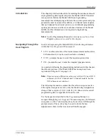
Powering Up
Because the Model GS868 does not have an ON/OFF switch, it will
power up as soon as the connected power source is energized.
Note:
For compliance with the European Union’s Low Voltage
Directive (73/23/EEC), this unit requires an external power
disconnect device such as a switch or circuit breaker. The
disconnect device must be marked as such, clearly visible,
directly accessible, and located within 1.8 m (6 ft) of the
Model GS868.
Immediately upon power up, the Model GS868 displays the GE logo
and the software version in the left pane of the display window. The
Model GS868 performs a series of internal checks and display the
results in the right pane of the display window.
Note:
If the Model GS868 fails any of the internal checks, try
disconnecting the power and then re-powering the unit. If the
Model GS868 continues to fail any of the internal checks,
contact the factory for assistance.
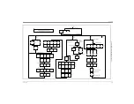
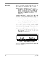
After successfully performing the internal checks, the Model GS868
begins taking measurements. The power up display is replaced by a
measurement mode display similar to that shown in Figure 3-1 below.
Note:
As a minimum, the system and pipe parameters (for each
installed channel of a 2-channel meter) must be entered before
the Model GS868 can display valid data. Refer to Chapter 2,
Initial Setup
, for specific instructions.
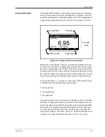
Figure 3-1: A Typical Measurement Display
Proceed to the next section for a description of the components of the
Model GS868 display screen.
Velocity
Volumetric
m/s
SCM/M
6.95
1038.7
SITE1 PIPE1
SITE1 PIPE1
VEL
VOLUM
-TOTL
+TOTL
Содержание DigitalFlow GS868
Страница 6: ...Chapter 1...
Страница 28: ...Chapter 2...
Страница 40: ...Chapter 3...
Страница 41: ...Operation Introduction 3 1 Powering Up 3 2 Using the Display 3 3 Taking Measurements 3 5...
Страница 49: ...Chapter 4...
Страница 50: ...Specifications General 4 1 Electrical 4 2 Operational 4 4 Transducer 4 4 Flowcell 4 5...
Страница 56: ...Appendix A...
Страница 57: ...CE Mark Compliance Introduction A 1 Wiring A 1 External Grounding A 1...
Страница 59: ...Appendix B...
Страница 60: ...Data Records Option Cards Installed B 1 Initial Setup Data B 2...
Страница 64: ...Appendix C...
Страница 65: ...Optional Enclosures Introduction C 1 Rack Mount Enclosure C 1 Rack Mount Wiring C 1 Rack Mount Front Panel C 2...
Страница 71: ...Appendix D...
Страница 72: ...Measuring P and L Dimensions Introduction D 1 Measuring P and L D 1...


