


March 2008
1-10
Installation
Wiring the 0/4-20 mA
Analog Outputs
The standard configuration of the Model GS868 flowmeter includes
two isolated 0/4-20 mA analog outputs (designated as A and B).
Connections to these outputs may be made with standard twisted-pair
wiring. The current loop impedance for these circuits must not exceed
550 ohms.
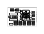
Refer to Figure 1-10 on page 1-20 for the location of terminal block
I/O
and wire the terminal block as shown.
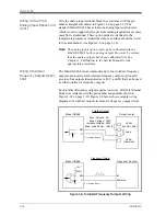
Wiring the Serial Port
The Model GS868 is equipped with a built-in serial communications
port. The standard port is an RS232 interface, but an optional RS485
interface is available upon request. Proceed to the appropriate sub-
section for wiring instructions. For more information on serial
communications, refer to the
EIA-RS Serial Communications
Manual
(916-054).
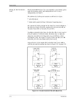
Wiring the RS232 Interface
The RS232 communications port provides a serial interface for
connecting the Model GS868 flowmeter to a printer, an ANSI
terminal or a personal computer.
The RS232 serial interface is wired as Data Terminal Equipment
(DTE), and the signals available at the Model GS868
RS232
terminal
block are shown in Table 1-1 below. Refer to Figure 1-8 on page 1-16
to locate terminal block
RS232
and complete the following steps to
wire the terminal:
1.
Use the information in Table 1-1 below to construct a suitable
cable for connecting the Model GS868 to the external device. If
desired, an appropriate cable may be purchased from GE.
2.
Wire the flying leads end of the cable to terminal block
RS232
and
connect the other end of the cable to the printer, ANSI terminal or
personal computer.
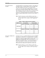
After the wiring has been completed, consult the User’s Manual for
the external device to configure it for use with the Model GS868.
Table 1-1: RS232 Connection to DCE or DTE Device
RS232
Pin #
Signal Description
DCE
DB25
Pin #
DTE
DB25
Pin #
DTE
DB9
Pin #
1
RTN (Return)
7
7
5
2 TX
(Transmit)
3
2
3
3
RX (Receive)
2
3
2
4
DTR (Data Terminal Ready)
20
20
4
5
CTS (Clear to Send)
4
5
8
Содержание DigitalFlow GS868
Страница 6: ...Chapter 1...
Страница 28: ...Chapter 2...
Страница 40: ...Chapter 3...
Страница 41: ...Operation Introduction 3 1 Powering Up 3 2 Using the Display 3 3 Taking Measurements 3 5...
Страница 49: ...Chapter 4...
Страница 50: ...Specifications General 4 1 Electrical 4 2 Operational 4 4 Transducer 4 4 Flowcell 4 5...
Страница 56: ...Appendix A...
Страница 57: ...CE Mark Compliance Introduction A 1 Wiring A 1 External Grounding A 1...
Страница 59: ...Appendix B...
Страница 60: ...Data Records Option Cards Installed B 1 Initial Setup Data B 2...
Страница 64: ...Appendix C...
Страница 65: ...Optional Enclosures Introduction C 1 Rack Mount Enclosure C 1 Rack Mount Wiring C 1 Rack Mount Front Panel C 2...
Страница 71: ...Appendix D...
Страница 72: ...Measuring P and L Dimensions Introduction D 1 Measuring P and L D 1...


