CamPlus 2 Plastic Dome IP Camera
Installation Manual
16
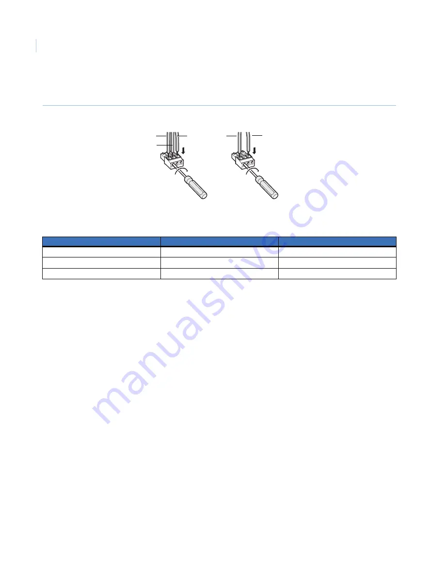
c. Tighten the screws to secure the inserted power wires. Make sure that the exposed wires are
completely hidden after tightening the screws (
Figure 19
).
Figure 19. Power cord plug
Table 1
shows the power plug terminals and the related wires.
d. Insert the power plug into the power terminals on the mounting side of the camera. Make sure the
power plug is inserted into the power terminals firmly.
Power over Ethernet (PoE).
When using PoE, connect a LAN cable (CAT5 or better) between a PoE
device (such as a PoE hub) and the network connector of the camera.
•
Use all four pairs (eight pins) of the LAN cable.
•
The maximum cable length is 328 ft. (100 m).
•
Make sure the PoE device you use is compliant with IEEE802.3af standard.
•
When connecting both the 12 VDC/24 VAC power supply and the PoE device for power supply,
the PoE will be used for power supply.
•
If the LAN cable is disconnected, wait at least 2 seconds before re-inserting the cable to ensure the
PoE device supplies power.
3. Connect a LAN cable (CAT5 or better) to the network connector on the mounting side of the camera
(
Figure 20
).
Table 1.
Power plug terminals
Power plug
24 VAC in
12 VDC in
A
2 N
-
B
GND
NC
C
1 L
+
A B
C
A B
C
12 VDC
24 VAC
C
B
-
+
A


