


GE H
EALTHCARE
D
IRECTION
5194296-100, R
EVISION
10
LOGIQ B
OOK
XP S
ERIES
B
ASIC
S
ERVICE
M
ANUAL
4-18
Section 4-3 - General Procedure
4-3-9-3
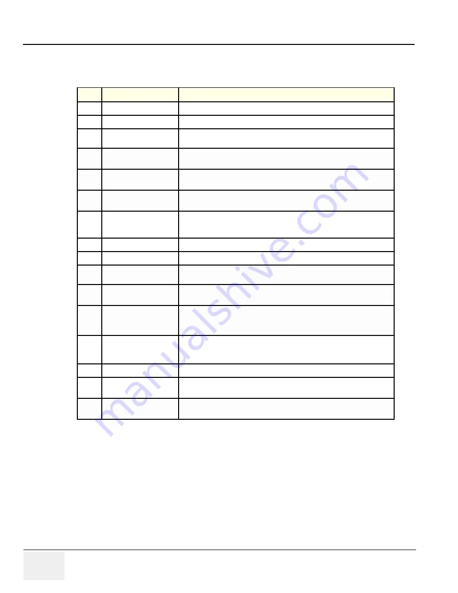
Color Flow Mode Softemenu Key
Table 4-8
Color Flow Mode Softmenu Key
Step
Task
Expected Result(s)
1
Threshold
Threshold assigns the gray scale level at which color information stops.
2
Packet Size
Controls the number of samples gathered for a single color flow vector.
3
Select Color maps
Allows a specific color map to be selected. After a selection has been made, the
color bar displays the resultant map.
4
Adjust Frequency
Enables the adjustment of the probe’s operating frequency. Press Frequency and
select desired value. The selected frequency is displayed in the status window.
5
Set Frame Average
Averages color frames. Press Frame Average up/down to smooth temporal
averaging.
6
Color Invert
Views blood flow from a different perspective. Press Invert to reverse the color
map.
7
Adjust LIne Density
Trades frame rate for sensitivity and spatial resolution. If the frame rate is too
slow, reduce the size of the region of interest, select a different line density
setting, or reduce the packet size.
8
Activate Spatial Filter
9
Activate ACE
Eliminates the motion artifacts. Press Ace to activate.
10
Adjust Quick angle
Slants the Color Flow region of interest or the Doppler line to obtain a better
Doppler angle.
11
Move Baseline
Adjusts the baseline to accommodate faster or slower blood flows to eliminate
aliasing.
12
Change PRF
(Pulse Repetition
Frequency)
Velocity scale determines pulse repetition frequency. If the sample volume gate
range exceeds single gate PRF capability, the system automatically switches to
high PRF mode. Multiple gates appear, and HPRF is indicated on the display.
13
Focus Position
Increases the number of transmit focal zones or moves the focal zone(s) so that
you can tighten up the beam for a specific area. A graphic caret corresponding to
the focal zone position(s) appears on the right edge of the image.
14
Capture
15
Power output
Optimizes image quality and allows user to reduce beam intensity. 10%
increments between 0-100%. Values greater than 0.1 are displayed.
16
Wall Filter
Wall Filter insulates the Doppler signal from excessive noise caused from vessel
movement.


