
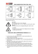


TIRE CHANGER FOR TRUCK TWC-1600
18
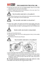
Insert the valve through the hole and fix it with its locking ring.
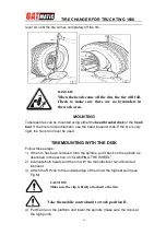
15)Place the inner tube in the center well of the rim (NB: to facilitate this, turn
the spindle clockwise).
16)Turn the spindle until the valve is at the bottom (6 o’clock).
17)Inflate the inner tube a little (until it has no folds) so as not to pinch it while
mounting the second bead.
18)Attach an extension to the valve and then remove the locking ring.
NB: The purpose of this operation is to allow the valve to be loose so that
it is not ripped out during second bead mounting.
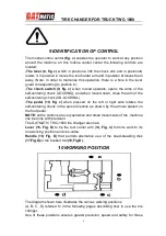
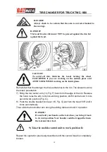
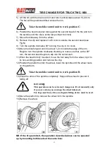
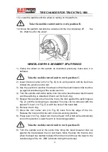
19)Move the tool carrier arm (14, Fig. D) to its working position.
20) Bring the tool forward until the red reference dot is lined up with the outside
edge of the rim and about 5 mm from it.
21)Pull back on this lever which will guide the bead into center well. Continue to
turn the spindle until the tire is completely mounted on the rim.
22)Tip the tool carrier arm to its non-working position.
23)Position the platform directly under the wheel and lower the spindle until the
wheel rests on the platform.
24) When the wheel is resting on the platform, check to make sure the valve is
perfectly centered with its hole. If it is not, turn the spindle slightly to adjust
the position. Fix the valve with its locking ring and remove the extension.
25) Close the arms of the spindle completely. Support the wheel to prevent it
falling off.
26) Move the platform to release the wheel from the spindle.
27) Remove the wheel.
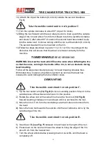
Take the mobile control unit to work position C.
DANGER!
This operation can be extremely dangerous.
Do it manually only if you are certain you can keep the wheel
balanced.
For large and heavy tires an adequate lifting device must be used.


