- 62 -
Tighten set screw to lock focus in place.
Be sure to test the focus of the camera with the Polycarbonate Dome in front of the lens
before making final adjustment. Some cameras may be slightly out of focus when the
Polycarbonate cover is put back on. Should this occur, simply loosen the set screw on the lens,
turn the lens 1/8 of a turn counter clockwise and tighten screw.
Changing
Changing
Changing
Changing the
the
the
the Camera Lens.
Camera Lens.
Camera Lens.
Camera Lens.
Remove Outer Dome Cover and Polycarbonate Dome by removing the two hex
screws with the supplied Hex Key.
Remove lens by loosening set screw, then turning
lens counter clockwise, replace with new lens.
Focus Camera as per ‘Focusing Camera Lens’.
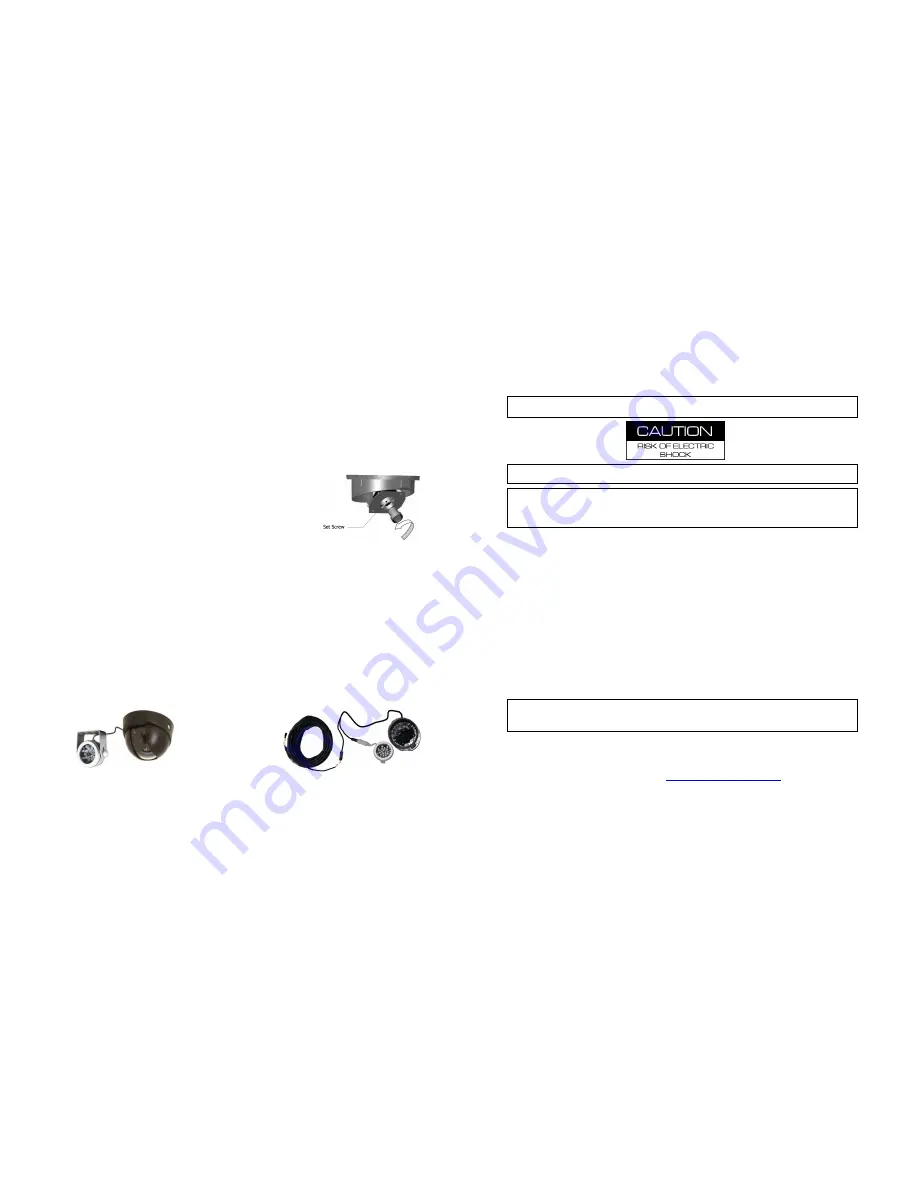
Figure 42: Changing the CAMICAGSC Camera Lens.
Recommended Location for the IR Illuminator
Recommended Location for the IR Illuminator
Recommended Location for the IR Illuminator
Recommended Location for the IR Illuminator
....
Please Note:
Please Note:
Please Note:
Please Note: Only use external IR (P/N: IR20) with Dome Camera (P/N: CAMICAGSC). DO
NOT use IR (P/N: IR20) in conjunction with a S-Series Camera.
Be sure to stagger the IR relevant to the front camera to allow easier access to the
camera dome screws and IR Illuminator screws.
Generally at the front of the Bus to the drivers side of the front camera, as close to
the center as possible.
Avoid areas where artificial light may cause “confusion” for the IR Illuminator which
will affect the proper function of the Illuminator.
Position the IR Illuminator so there’s an unobstructed view to the back of the bus.
Illuminator should be aimed towards the Emergency Exit sign at the back of the bus.
Bracket must be securely fastened to the ceiling or bulkhead.
Power connector should be inside bulkhead or pushed into ceiling cavity.
Ensure minimal exposure of the harness.
IR Quick Connect CAB000085
Figure 43 : IR and Camera.
- 7 -
Important Safeguards and Warnings
Important Safeguards and Warnings
Important Safeguards and Warnings
Important Safeguards and Warnings....
Remove Main Power Fuse
Remove Main Power Fuse
Remove Main Power Fuse
Remove Main Power Fuse or Disconnect Vehicle Batteries
or Disconnect Vehicle Batteries
or Disconnect Vehicle Batteries
or Disconnect Vehicle Batteries Prior To Any Electrical Work
Prior To Any Electrical Work
Prior To Any Electrical Work
Prior To Any Electrical Work
Or Jump Starting The Vehicle.
Or Jump Starting The Vehicle.
Or Jump Starting The Vehicle.
Or Jump Starting The Vehicle.
DO NOT USE THE POWER BUTTON ON THE REMOTE CONTROL
DO NOT USE THE POWER BUTTON ON THE REMOTE CONTROL
DO NOT USE THE POWER BUTTON ON THE REMOTE CONTROL
DO NOT USE THE POWER BUTTON ON THE REMOTE CONTROL
Firmware updates (available from www.gatekeeper-systems.com when released) are
system specific, I.E. NiTRO-X
400 firmware updates must only be applied to a NiTRO-X
400 system. If this firmware is applied to any other system warranty will be void
warranty will be void
warranty will be void
warranty will be void.
Do Not remove the SD card from the NiTRO
400 series or NiTRO-X
400 series until
the record extend has completed and the Yellow LED (Figure 4) is no longer illuminated,
or, use the Stop button on the front of the DVR. Failure to do this will result in permanent
damage to the SD card.
Do not remove the cover of the NiTRO
400 series or NiTRO-X
400 series as this will
void any warranty.
A Class 6 card is recommended.
The tamperproof retaining cage for the NiTRO-X
400 has a different locking mechanism
and the key set for a NiTRO-X
400 system will not work with a NiTRO
400 series
system, and vise versa.
When a system has shipped with a GPS antenna, ensure that the GPS antenna is
mounted externally on the roof of the bus, magnetic side down.
The NiTRO
400 series and NiTRO-X
400 series are designed for indoor use only. Do
Not expose to water or moisture.
When installing a NiTRO
400 DVR unit in an existing NiTRO-X
400 installation cables,
CAB000268, 4 pin to 6 pin Power Adapter Cable MUST be utilized (See Appendix for
more information).
If at any time there is a question about how to proceed, contact Gatekeeper Systems Inc.
at 1-888-666-4833 or 604-864-6187 immediately for directions. Review all installation
documentation, including technical bulletins. Additional Technical Bulletins and Product
Tutorials can be found in the Gate section of
www.gatekeeper-systems.com


