- 20 -
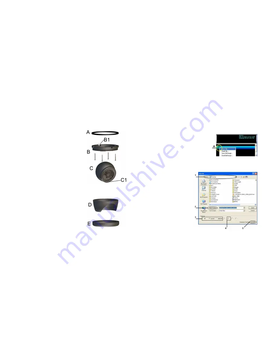
A.
A.
A.
A.
Rubber G
Rubber G
Rubber G
Rubber Gasket
asket
asket
asket. B.
. B.
. B.
. B. Base Plate
Base Plate
Base Plate
Base Plate. C.
. C.
. C.
. C. Camera Ball
Camera Ball
Camera Ball
Camera Ball.
.
.
.
D.
D.
D.
D. Camera Collar
Camera Collar
Camera Collar
Camera Collar. E.
. E.
. E.
. E. Retainer Ring
Retainer Ring
Retainer Ring
Retainer Ring
1.
Disassemble the S-Series camera into its five major parts,
A, B, C, D, E and carefully place all parts in a clean work
area.
2.
Position the Base Plate (B), in the mounting location.
Ensure that there are no gaps between the Base Plate (B)
and the mounting surface. If there are gaps, relocate the
camera to a position where there are no gaps.
3.
Note the location where the camera harness will come
though the bodywork of the vehicle. Drill a 3/8
th
hole in
this location. This 3/8
th
hole MUST be directly in the center
of the Base Plate (B) to allow for the terminal end of the
camera harness to correctly connect to the Camera Ball
(C). When access behind the camera is not possible, the
cable can be routed from the side through one of the cut
out notches B1 in the camera base.
4.
Center the supplied template guide over the 3/8” hole and
mark the location for the 4 screws used to secure the
camera base to the vehicle. Alternatively, center the
camera base over the 3/8” hole and mark the location of
the 4 screws used to secure the camera base to the
vehicle. In both cases, ensure that one of the camera cut
out notches, B1, is aimed at the viewing target. Drill a
suitable pilot hole to accept a #6 screw for each of the
supplied screws.
5.
Remove the backing on the rubber gasket (A) pad exposing the adhesive. Secure the Rubber Gasket,
adhesive side down to the Base Plate (B). The Rubber Gasket is supplied to reduce the possibility of any
rattling noise between the camera and vehicle that may be picked up by the microphone. Using the
supplied Tek Screws, secure the camera base to the vehicle.
6.
Connect the Camera Ball Molex connector to the
connector at the end of the camera harness. Hold the
Camera Ball firmly against the Base Plate with the
Microphone, C1, pointing downwards. Position Camera
Collar (D) over Camera Ball (C) with the lens window
centered in the arched cut away in the Camera Collar.
7.
Hold Camera Collar (D) securely while threading on the
Retainer Ring (E) until finger tight. Be careful not to
cross-thread the components.
8.
To aim the Camera Ball (C), video from the camera can
be viewed by connecting a monitor to the back of the DVR
“AV-Out” port with a Video Adaptor Cable.
9.
Re-position Camera Collar (D) prior to tightening down the Retainer Ring (E) so that it does not interfere
with line of sight of the camera and IR LED’s in the Camera Ball (C). Ensure the Camera Ball and Harness
pigtail are not pinched or trapped between the Camera Ball (C) or the Base Plate (B), it must be able to
move freely.
- 49 -
Saving a Clip.
Saving a Clip.
Saving a Clip.
Saving a Clip.
There are two ways in which you can Save a video clip, one using the right-mouse button and
the other method uses the File Menu. Both methods use the same steps to first mark the
video you wish to take a clip of.
1.
Pause the video at the point of the video where you want the clip to start from.
2.
Single left-click on the Video Clip Graph where the yellow cursor bar is located.
3.
Drag the mouse to the right, the graph will be
highlighted in green, (A). The Subtitle
information panel will reflect information
regarding the clip being taken. Release mouse
at end point.
4.
Right-click on the created green section in the
video clip graph and choose Save Clip, or,
choose File, Save
Video Clip.
Figure 37 : Marking a Clip.
Once you have selected the clip which you require, a new pop-up window will appear. This is
the Save As dialog box, Figure 38, enter all the relevant information and make your choices,
and then choose Save.
1.
Ensure that you know where
the file is being saved to, this
will help with retrieval later.
2.
The object name should be;
The Date and Time followed by
the bus ID, we recommend that
you accept the default.
3.
There is an option to select All;
Current camera view, or, a
combination of Selected
cameras.
4.
In this example we are going to
choose Current, which shows
in the greyed out box as
camera 2.
5.
Here you see the estimated
size of the resulting file for the
clip created.
Once options 1 and 3 are set, click
on Save.
Figure 38 : Saving A Video Clip


