background image


-17- 

Installing the Dome Camera

Installing the Dome Camera

Installing the Dome Camera

Installing the Dome Camera....    

1.


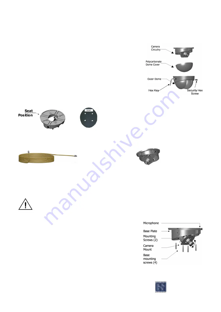
Disassemble the dome camera by removing the outer polycarbonate 
dome.  Loosen Phillips screws to allow camera board to move freely. 

 
2.


Ensure the included gasket is in place between dome baseplate and 
mounting surface. This gasket is required as it acts as a cushion to 
absorb vibration and aid in elimination of wind noise from the roof of the 
bus. Determine seat position for camera harness and insert camera 
harness into seat position. 


Figure 

Figure 

Figure 

Figure 10

10

10

10: Removing Outer and Polycarbonate Dome.

: Removing Outer and Polycarbonate Dome.

: Removing Outer and Polycarbonate Dome.

: Removing Outer and Polycarbonate Dome.    


Camera Gasket 

Use the FRONT label as your guide. Ensure the Lens/Microphone 
assembly is located directly above the FRONT label. 

Figure 

Figure 

Figure 

Figure 11

11

11

11: Camera Seat Position.

: Camera Seat Position.

: Camera Seat Position.

: Camera Seat Position.    

Attach the Molex connector from camera harness to the Molex connector attached to the camera circuitry. 


3.


If mounting to Bulkhead of the bus follow ‘Bulkhead Mount’ instructions on the following page. 

4.


Tuck attached camera harness behind the camera circuitry and then mount base with the four screws supplied 
(Figure 12, Page 21). 

5.


Focus camera by referring to ‘Focusing Camera Lens’ on the following page. 

6.


After final check re-attach Polycarbonate dome cover and outer dome with hex screws.   


Do not clean polycarbonate dome with any agents. 

Bulkhead

Bulkhead

Bulkhead

Bulkhead Mount

 Mount

 Mount

 Mount....    


Remove the two bracket mounting screws. 


Rotate camera mount 180° (upside down) and reattach to base 
plate. 

Return to step 4 of ‘Installing the Dome Camera’ 


Ceiling Mo

Ceiling Mo

Ceiling Mo

Ceiling Mount

unt

unt

unt - Microphone should be situated facing back of bus 


Bulkhead

Bulkhead

Bulkhead

Bulkhead Mount

 Mount

 Mount

 Mount - Microphone should be situated facing floor. 


  Figure 

Figure 

Figure 

Figure 12

12

12

12: Mounting the Camera

: Mounting the Camera

: Mounting the Camera

: Mounting the Camera....    


Содержание Digital Smart Recorder NiTRO 900

Страница 1: ...NiTRO 900 Manual Version 1 8 1 1 Safety Security Peace of Mind...

Страница 2: ...View 18 Changing Camera Lens 18 Check For 19 Quick Configuration Settings for Installers 20 Setting the Configuration 21 Basic Configuration 21 Advanced Configuration 24 System Configuration 29 Record...

Страница 3: ...Video Clip 48 Extracting Still Image 48 Setting the Recorder Configuration 49 Saving Configuration 52 Loading Configuration on Recorder 52 Check for Updates 52 Upgrading Software on the NiTRO 900 54...

Страница 4: ...guration 19 Figure 17 Alternate Four Camera Configuration 19 Figure 18 Cloning a comrad 32 Figure 19 Record Screen 33 Figure 20 Playback Display 34 Figure 21 Downloading Clips To A comrad 35 Figure 22...

Страница 5: ...eader that not adhering to the instruction could result in bodily harm equipment damage or data loss Alerts the reader to a strong recommendation that will enhance the performance of the recorder A us...

Страница 6: ...of the GSX System either physically or by USB Do not remove the cover of the NiTRO 900 Doing so will directly result in voiding the manufacturer s warranty If your NiTRO 900 requires repair contact Ga...

Страница 7: ...nt hard drive and storage device Isolation Suspension System Thermal Intelligence Direct Connect USB 2 0 Power Guard Smart Flag Alarm Verification LCD Smart Search User friendly and convenient way to...

Страница 8: ...rview Overview Check List Check List Check List Check List Use the provided check list to ensure that you have received all the components required for your complete NiTRO 900 Digital Smart Recorder M...

Страница 9: ...05 Camera Alignment Cable CAB000157 DC to DC Cable CAB000149 RCA Single patch Cable DVRWPCRC 150 Direct Camera Connect Cable CAMWHAVIDEOCABLE A A A Ac c c ccessories cessories cessories cessories The...

Страница 10: ...nector Pin Molex Connector Power input 3 3 3 3 Mouse Input Mouse Input Mouse Input Mouse Input Not Used 4 4 4 4 Keyboard Keyboard Keyboard Keyboard Connect keyboard to navigate through menus instead o...

Страница 11: ...d Lead Lead Lead Y Y Y Y WIRE WIRE WIRE WIRE COLOR COLOR COLOR COLOR 7 7 7 7 Lead Lead Lead Lead Z Z Z Z FUSE PANEL CONNECTION FUSE PANEL CONNECTION FUSE PANEL CONNECTION FUSE PANEL CONNECTION 1 Extra...

Страница 12: ...of temperature range 5 5 5 5 comrad comrad comrad comrad Power LED Power LED Power LED Power LED Lit when the NiTRO system is powered up Shutdown the NiTRO System prior to removal of the comrad Do not...

Страница 13: ...cate site for all other accessories ie Alarm Button Record LED optional Mount the Isolation Suspension System plate Run Power harness through enclosure to destination Connect the constant power on the...

Страница 14: ...and moisture Ensure sufficient airflow for enclosure fan and vents Solid flat mounting surface Recommended Location for the IR Illuminator Recommended Location for the IR Illuminator Recommended Loca...

Страница 15: ...s connected to Green lead 9 on the Four conductor cable on the Sensor Harness 11 1 Alarm Button 2 Record LED 3 Record LED Red Lead 4 Record LED White Lead 5 Alarm Button Red Lead 6 Alarm Button Black...

Страница 16: ...the Camera Harness es Route the camera harness es and accessory harness es Always use grommets when running the harness through sheet metal holes Avoid excessively tight bends especially around metal...

Страница 17: ...a Seat Position Camera Seat Position Camera Seat Position Attach the Molex connector from camera harness to the Molex connector attached to the camera circuitry 3 If mounting to Bulkhead of the bus fo...

Страница 18: ...focus when the Polycarbonate cover is put back on Should this occur simply loosen the set screw on the lens turn the lens 1 8 of a turn counter clockwise and tighten screw Adjusting the Field of View...

Страница 19: ...pening in base Use existing wire paths wherever possible ie radio speakers etc Avoid excessively tight bends especially around metal surfaces Always use grommets when routing through sheet metal holes...

Страница 20: ...n and then select VIDEO ONLY This will ensure that the customer will receive the system without any previous video on their comrad All other settings are set by default refer to the following pages fo...

Страница 21: ...guration Basic Configuration Basic Configuration There are seven menus under the BASIC sub menu The menus are defined below Refer to the following pages for a detailed description of how to use each m...

Страница 22: ...e ID can be set using UPPERCASE lowercase alphabet letters numbers 0 through 9 space and dash with a maximum of 20 characters EXIT EXIT EXIT EXIT Press the blue menu button to exit Set ID OTHER OTHER...

Страница 23: ...he blue menu button to exit the Set Date menu OTHER OTHER OTHER OTHER The video file name includes the date and time of the beginning of the file The recorder files video on a first in first out FIFO...

Страница 24: ...r ignored This setting determines the microphone audio level input This setting determines the audio level output The Subtitle Position allows you to position the subtitle text on the top or bottom of...

Страница 25: ...blue menu button to exit and return to the Advanced sub menu DEFAULT CONDITION DEFAULT CONDITION DEFAULT CONDITION DEFAULT CONDITION US PURPOSE PURPOSE PURPOSE PURPOSE If the recorder is wired to moni...

Страница 26: ...rrow to advance to the next menu or left arrow to advance to the previous menu Press the blue menu button to exit and return to the Advanced sub menu OTHER OTHER OTHER OTHER None the recorder will rec...

Страница 27: ...meras ENTRY ENTRY ENTRY ENTRY Use the plus and minus keys to toggle between C C C Color olor olor olor or B B B Black lack lack lack W W W White hite hite hite EXIT EXIT EXIT EXIT Use the right arrow...

Страница 28: ...nged to DOOR the letter D would be displayed ENTRY ENTRY ENTRY ENTRY Press Go to enter the Sensor Setup menu Use the plus and minus sign keys to increment each character Use the left or right arrow ke...

Страница 29: ...return to the Advanced sub menu OTHER OTHER OTHER OTHER The speed units used will be correct according to the units configured in the Set Units menu ie if the unit is set to Metric units the speed wil...

Страница 30: ...Laptop via the rear Ethernet port the IP address will be displayed under IP0 This address is used to connect to the recorder over the network ENTRY ENTRY ENTRY ENTRY No entry data already displayed o...

Страница 31: ...er gets a new update via Check for Updates or Upgrades copied from another comrad the new version of software can be confirmed here ENTRY ENTRY ENTRY ENTRY No entry data already displayed on screen EX...

Страница 32: ...orrupt hard drives or to upgrade other units Remember cloning will format the drive first so do not use clone if you want to keep the video stored on the drive When using the Dual Head USB Cable ensur...

Страница 33: ...s the index will show 1 10 2 10 10 10 Method II Date Time Input the date and time of the video file you want to watch Playback skips to the video that is closest to that time All videos are indexed by...

Страница 34: ...lay back Figure Figure Figure Figure 20 20 20 20 Playback Display Playback Display Playback Display Playback Display Rew Fwd Buttons Rew Fwd Buttons Rew Fwd Buttons Rew Fwd Buttons When you press Rew...

Страница 35: ...ile The Save 10 minutes automatically extracts a clip up to 5 minutes of video before the current position and up to 5 minutes of video after the current position 1 Press Pause when you reach the midd...

Страница 36: ...blue menu button or Cancel to exit the Shutdown menu MESSAGES MESSAGES MESSAGES MESSAGES Shutting down appears when the system is safely shutting down The system takes roughly 15 seconds to fully pow...

Страница 37: ...the rear Ethernet port comrad comrad comrad comrad Only to Computer Only to Computer Only to Computer Only to Computer Power down the recorder and remove the comrad unit by pulling firmly on the fron...

Страница 38: ...deo files For first time connection you will need to install MAXVIEW software by double clicking on the setup exe setup exe setup exe setup exe file Refer to MAXVIEW Installation section for details o...

Страница 39: ...m IP1 1 Address Bar 2 setup exe Figure Figure Figure Figure 25 25 25 25 Browsing The Recorder On A Computer Browsing The Recorder On A Computer Browsing The Recorder On A Computer Browsing The Recorde...

Страница 40: ...1 e g 192 168 0 1 e g 192 168 0 172 72 72 72 Simply enter two backslashes followed by that address into the address bar in Windows Explorer e g e g e g e g 192 168 0 1 192 168 0 1 192 168 0 1 192 168...

Страница 41: ...sor with 32 MB dedicated video RAM Connection Connection Connection Connection USB 1 1 USB 2 0 100 Mbps Ethernet Network Card TCP IP Protocol For best system performance we recommend that your PC exce...

Страница 42: ...een to the left does not automatically pop up browse using Windows Explorer and double click on the removable drive GSX NiTRO Videos and double click on the setup exe setup exe setup exe setup exe fil...

Страница 43: ...r We recommend that the software is installed under Program Files press Next to proceed Start Installation Press Next to proceed Installing Files We recommend you do not abort installation process aft...

Страница 44: ...ps and extract still images 6 Sensor List Figure Figure Figure Figure 27 27 27 27 MAXVIEW MAXVIEW MAXVIEW MAXVIEW Operation Operation Operation Operation Opening Video Files Opening Video Files Openin...

Страница 45: ...is moveable and resizable Figure Figure Figure Figure 29 29 29 29 Displaying The GPS Map Displaying The GPS Map Displaying The GPS Map Displaying The GPS Map To view where the vehicle is in relation t...

Страница 46: ...ck on the Time Graph and the Vehicle Locator will appear in the GPS Data window With the playback video still paused if you left click again in a different position along the Time Graph the Vehicle Lo...

Страница 47: ...can t be heard Figure Figure Figure Figure 33 33 33 33 Adjusting Sound Balance In Windows XP Adjusting Sound Balance In Windows XP Adjusting Sound Balance In Windows XP Adjusting Sound Balance In Win...

Страница 48: ...the video you wish to take a clip of 1 Pause the video at beginning of the clip you want to save 2 Left click on the Video Clip Graph where the yellow cursor is located 3 Drag mouse to the right the...

Страница 49: ...VIEW rather than the LCD screen To open the configuration menu first Double click on the file located in the configuration list The filename is the ID name and by default is the factory serial number...

Страница 50: ...rations Audio Volume In Max Cameras Record Delay Record Extend Dwell Time Sensor Configuration You can change the name of each sensor from the default name Also assign a specific sensor to a specific...

Страница 51: ...e camera selection Please note When setting the video to Color or to Black and White if there are multiple cameras connected to the NiTRO 900 with one being a color camera this setting must be set to...

Страница 52: ...scroll to the desired configuration file Finally press the blue menu button to load All files recorded from this point forward will use this configuration Check for Updates Check for Updates Check for...

Страница 53: ...es are automatically copied in to the upgrade folder on the comrad comrad has been successfully upgraded you may now update another comrad or use this comrad to copy upgrade files to another recorder...

Страница 54: ...he NiTRO 900 The LCD will display Copying Upgrades for a moment When the upgrade files are finished copying shutdown and restart the recorder To verify that the upgrade was successful go to Configurat...

Страница 55: ...When I view video there is only a black deo there is only a black deo there is only a black deo there is only a black screen screen screen screen Make sure all camera harnesses are connected to the v...

Страница 56: ...Once the ID has been set press the BLUE menu button to the left of the LCD Once the BLUE menu button has been pressed you will see the screen change to Saving Config A confirmation screen will appear...

Страница 57: ...uit 12V 6 Brown User customizable sensor optional 12V 7 White Connect to Warning light Amber circuit 12V B B B B Alarm LED Alarm LED Alarm LED Alarm LED Harness Harness Harness Harness 4 wires 1 Red 1...

Страница 58: ...58 Notes Notes Notes Notes...

Страница 59: ...59...

Страница 60: ...60...

Страница 61: ...Gatekeeper Systems Installation and Operating Manual This warranty does not apply to any damage to the Gatekeeper Systems product that is the result of improper maintenance or to any Gatekeeper System...

Страница 62: ...I GSI GSI Canada Canada Canada Canada 301 31127 Wheel Avenue Abbotsford BC V2T 6H1 Canada GSI GSI GSI GSI USA USA USA USA 446 Harris Road Sumas WA 98295 USA Sales Technical Support Sales Technical Sup...

Отзывы: