Garnet PC-900G Скачать руководство пользователя страница 13

13

7.2 Description of the module:

Communication formats:

The WiFi communicator is designed to send alarm signals to monitoring receivers that 

receive events under the DC1 and SDC2 communication protocols. 

Panel control modes:

The WiFI communicator allows the panels to be controlled through two methods, one 

method is by using the Garnet Control application.

7.3 Light indications of states

The embedded WiFi communicator incorporates a variety of LEDs to

report the different states of the communicator.

There are LEDs that indicate the signal strength of the Wi-Fi network, the results of

reports to the server and to the monitoring station.

Explanation of light indications:

There are two groups of LEDs, the ones that indicate the signal strength of the con-

nection with the

Wifi network and those reporting the results of Wifi communications.

Wifi Signal Indicator LEDs

These LEDs indicate whether or not the communicator is connected to a network.

If the communicator is connected to a Wifi network, the blue LED representing the 

Wifi Antenna will indicate its signal strength by flashing as many times as its signal 

level.

The number of flashes represents the signal level, with 1 flash for a very low signal 

level and 5 flashes to indicate the maximum signal level.

If the communicator is not connected to a Wifi network, the red “No Signal” LED will be 

on indicating that the communicator is not connected to a Wifi network.

Communication indicator LEDs

The communicator is prepared to communicate via a Wifi connection.

In any of the cases, when there is a communication or some kind of report, its result 

will be indicated by the leds representing the communications.

When a report is made to the monitoring station or in residential format, the result 

will be represented by two LEDs, one representing the successful report (ACK) or the 

one indicating communication failure (NAK).

When the communicator reports a supervision to monitoring or to the server, it will 

light both LEDs simultaneously.

7.4 

Programming the Communicator and Panel from the Garnet Programmer app

The communicator is programmed via the “Garnet Programmer” app. This app also 

allows the Garnet alarm panels to be programmed.

To download the programming app, scan the following QR codes as appropriate or 

search the download shop for the Garnet Programmer app.

Follow the steps below:

1) 

Press the 

“AP ENABLE”

 button on the nameplate.

This will cause the communicator to generate a WiFi network for a period of 5 minu-

tes.

2) 

Search your phone for available WiFi networks and connect to the WiFi network 

whose name is “PC-900xxxxxx”. XXXXXXXX being the last 6 digits of the communica-

tor’s mac.

3)

 Enter the default network password: admin1234.
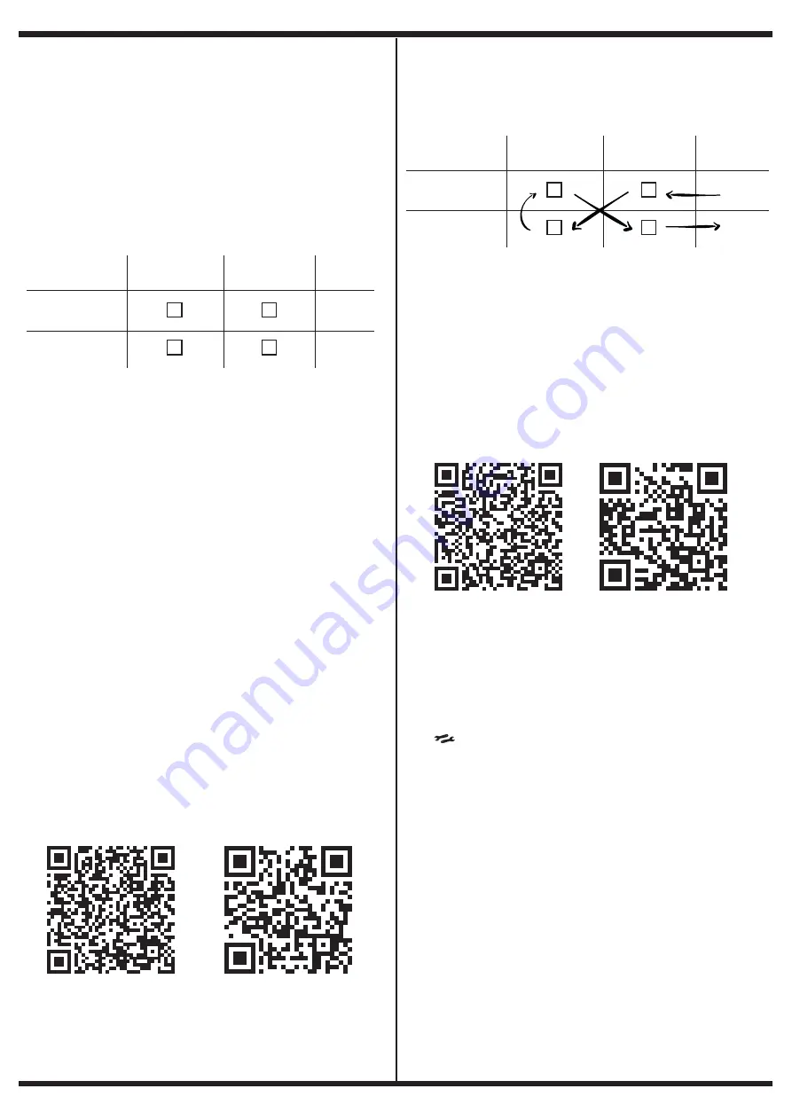
4) 

Once the communicator enters programming mode. The LEDs will behave as 

follows

If this result is not achieved. Repeat the steps from the beginning.

It is essential that the mobile phone is in “Airplane” mode at the time of connection.

against the module’s WiFi network

5) 

Once ready, open the Garnet Programmer application and follow the instructions 

you wish to program.

NOTE:

 In programming the communicator within the “status” screen you should make 

a note of the System Number as it will be used in the next step.

7.5 Enabling Telephones or Terminals

To enable the phones, you must first ensure that the communicator was previously 

configured and has a successful connection to the internet through a Wifi connection 

or by using mobile data.

From your phone’s shop download the application for the User 

“Garnet Control”.

Once you have downloaded the application you will need to register using your 

personal details.

Then within the application press the “+” button to add a new system, you must enter 

the System Number obtained in the previous step, a name that identifies the alarm 

system that is installed and finally an icon.

You must then initiate the connection to your phone from the communicator. You will 

need to press the “AP ENABLED” button 3 times in a row, or if you have an LCD keypad 

press [           ] + 8 + 7.

Confirmation of successful enablement will be by flashing the top 4 antenna and 

communications indication LEDs. After this press the “Verify” button on your mobile 

phone.

In seconds your application will be ready for use

NOTE: 

The Garnet Control application allows up to 20 total users to be associated.

The main user that was associated will be listed as “Administrator”.

This user will be able to invite the remaining 19 users of the system with two different 

user categories:

• Main User:

This user can be defined by the administrator in terms of the roles and

permissions you have on the alarm panel.

For example: 

You can have a user as a family member who has all the functions of 

remote control and event reception checked. But I can also have a main user that only 

allows him to receive events.

• Secondary User:

This user does not allow attribute modifications. Only this user can view system 

cameras.

To invite users, go to the community tab.

Android 

Android 

iOs (iPhone)

iOs (iPhone)

  Antena Wifi      Comunic. WiFi

Signal 1-5

No Signal

ACK

NAK

  Antena Wifi      Comunic. WiFi

Signal 1-5

No Signal

ACK

NAK

Содержание PC-900G

Страница 1: ...EN ENGLISH PC 900G ALARM PANEL Quick programming guide...

Страница 2: ...ations which can damage electronic equipment such as security systems After a power interruption occurs immediately conduct a complete system test to ensure that the system is functioning as intended...

Страница 3: ...port 11 5 15 Fire Medical and Panic keys 11 5 16 Events Report 11 5 17 Zone Circuit Response 11 5 18 Communication Scenarios 11 5 19 How to operate communication scenarios 11 5 20 Reset to Factory Def...

Страница 4: ...k Data Bus BUS D485 It works through the RS 485 protocol its connection is made using 4 wires 2 for power supply and 2 for data The system is able to supervise each device connec ted to the bus and ge...

Страница 5: ...o the system via a 4 wire bus Up to 200m from the PC 900G panel A 512 log event memory with date and time of occurrence The memory can be viewed with the KPD 860 860RF and G LCD732 732RF keypads Autom...

Страница 6: ...Step 10 Test the System Fully test the system to ensure that all features and functions are operating as programmed 2 2 Terminal Descriptions Battery Connection BAT A 12V 4 7Ah rechargeable battery is...

Страница 7: ...nger supervise a module that has been removed from the system To remove the module disconnect it from the Bus and disable it in the 299 installer programming command 2 8 Zone Wiring For a complete des...

Страница 8: ...i n de falla est presente el indicador Falla se encender de modo intermitente Ver Tabla de Fallas segun indice 3 Bypass Zones This command is similar to pressing the Bypass key of the teclados KPD 860...

Страница 9: ...pe normally used by entry exit doors can be violated during the exit delay period without causing an alarm Once the exit delay has expired opening the zone will start the entry delay counter During th...

Страница 10: ...s armed 04 Output command maintained The output can be used as a switch Its state change can be controlled via a keypad see section 3 4 7 Keypad control of programmable outputs or by using the AC4 sof...

Страница 11: ...n scenarios are a neat alternative for organising communications The PC 900G panel has 2 communication scenarios Call Scenario N 1 Reports with Backups This scenario has one main output me dium and se...

Страница 12: ...ill indicate the zone where the sensor is working the memory location where it is recorded and the signal level 6 6 How to display the zones assigned to each sensor In order to visualise the zones whe...

Страница 13: ...e a WiFi network for a period of 5 minu tes 2 Search your phone for available WiFi networks and connect to the WiFi network whose name is PC 900xxxxxx XXXXXXXX being the last 6 digits of the communica...

Страница 14: ...l control modes The COM 900 COM 904 communicator allows the panels to be controlled through two methods one method is through the use of the Garnet Control application and the other method is via text...

Страница 15: ...3 451 1 451 OK CK Quick Arming Disarming 2 3 4A1 1 4A1 OP CL Auto Arming Failure 1 455 CI Recent closure 1459 CR Zone Bypass 1 57A 3 57A UB UU Group Bypass 1 574 3 574 BB BU Manual Test Report 1 6A1 R...

Страница 16: ...Partition No 1 1 Controls Partition No 1 Digit position 2 Partition Allocation No 2 0 No Control Partition No 2 1 Controls Partition No 2 Digit position 3 Partition Assignment No 3 0 No Control Parti...

Страница 17: ...de No 25 Attributes Default values 1 0 0 0 1 1 1 0 0 4 9 Positions 1 2 3 4 5 6 7 8 Command Number 050 User Code No 26 Attributes Default values 1 0 0 0 1 1 1 0 0 5 0 Positions 1 2 3 4 5 6 7 8 Command...

Страница 18: ...5 Positions 1 2 Command Number 086 Zone No 17 Configuration Default values 0 5 0 8 6 Positions 1 2 Command Number 087 Zone No 18 Configuration Default values 0 5 0 8 7 Positions 1 2 Command Number 088...

Страница 19: ...No 6 Attributes Default values 1 1 1 0 0 0 1 0 1 1 5 Positions 1 2 3 4 5 6 7 8 Command Number 116 Zone No 7 Attributes Default values 1 1 1 0 0 0 1 0 1 1 6 Positions 1 2 3 4 5 6 7 8 Command Number 117...

Страница 20: ...ed Digit position 4 Zone No 4 0 Disabled 1 Enabled Digit position 5 Zone No 5 0 Disabled 1 Enabled Digit position 6 Zone No 6 0 Disabled 1 Enabled Digit position 7 Zone No 7 0 Disabled 1 Enabled Digit...

Страница 21: ...igit position 3 Zone No 11 0 Disabled 1 Enabled Digit position 4 Zone No 12 0 Disabled 1 Enabled Digit position 5 Zone No 13 0 Disabled 1 Enabled Digit position 6 Zone No 14 0 Disabled 1 Enabled Digit...

Страница 22: ...0 5 1 6 2 Positions 1 2 3 Digit positions 1 3 Partition Siren Time The code must be 3 digits long Valid values are from 000 to 255 minutes Command Number 163 Time Interval for Crossing Zones Default...

Страница 23: ...on No 3 Default values 0 2 1 8 0 Positions 1 2 Command Number 181 PGM Configuration No 4 Default values 0 3 1 8 1 Positions 1 2 Command Number 182 PGM W Configuration No 1 Default values 0 0 1 8 2 Pos...

Страница 24: ...fault values 0 0 2 2 0 Positions 1 2 Digit position 1 2 Zone No Assignment to Input No 1 of Expander Module No 1 The code must be 2 digits long Valid values are 00 to 32 With the value 00 the zone is...

Страница 25: ...mber 245 Auxiliary Fault Counter BUS D485 Default values 0 8 2 4 5 Positions 1 2 Digit position 1 2 Auxiliary Fault Counter BUS D485 The code must be 2 digits long Valid values are 00 to 16 Note If yo...

Страница 26: ...the same way as Command No 260 Command Number 261 Partitioning Options No 2 Default Values 0 0 0 0 0 0 0 0 2 6 1 Positions 1 2 3 4 5 6 7 8 Command Number 262 Partitioning Options No 3 Default Values...

Страница 27: ...2 3 4 5 6 7 Command Number 292 Automatic Arming Days of Partition No 3 Default values 0 0 0 0 0 0 0 2 9 2 Positions 1 2 3 4 5 6 7 Command Number 293 Automatic Arming Days for Partition No 4 Default v...

Страница 28: ...n Zone Alarm Restore Alarm Report Digit position 3 Emergency Key Report Same Options as Alarm Reporting Restore in Zones Digit position 4 Coercion Reports Same options as in Alarm Restore Zone Reporti...

Страница 29: ...Scenario No 2 Simultaneous Reporting Defaults Values 0 0 0 0 0 0 0 0 3 7 1 Positions 1 2 3 4 5 6 7 8 Digit position 1 Future Use 0 Disabled 1 Enabled Digit position 2 Future Use 0 Disabled 1 Enabled D...

Страница 30: ...tions 1 2 Command Number 430 Remote Control Functions for Memory location No 1 Default values 0 0 0 0 4 3 0 Posiciones 1 2 3 4 Digit position 1 Functions of Button No 1 Memory position No 1 0 Arm Disa...

Страница 31: ...No 19 Default values 0 0 0 0 4 4 8 Positions 1 2 3 4 Command Number 449 Remote Control Functions for Memory location No 20 Default values 0 0 0 0 4 4 9 Positions 1 2 3 4 Command Number 450 Remote Con...

Страница 32: ...472 Remote Control Functions for Memory location No 43 Default values 0 0 0 0 4 7 2 Positions 1 2 3 4 Command Number 473 Remote Control Functions for Memory location No 44 Default values 0 0 0 0 4 7 3...

Страница 33: ...ons 1 2 3 4 Command Number 492 Remote Control Functions for Memory location No 63 Default values 0 0 0 0 4 9 2 Positions 1 2 3 4 Command Number 493 Remote Control Functions for Memory location No 64 D...

Страница 34: ...vision fault Led Z2 Tech N 2 supervision fault Led Z3 Tech N 3 supervision fault Led Z4 Tech N 4 supervision fault Led Z1 Link Failure Mobile Data Led Z2 Link failure Wifi Led Z1 Tamper tec N 1 Led Z2...

Страница 35: ...ly affects performance or does not permit proper inspection or testing to verify any warranty claim IV Products not covered by this warranty or otherwise out of warranty due to age misuse or damage wi...

Страница 36: ...36 NOTES...

Страница 37: ...37...

Страница 38: ...38...

Страница 39: ...39...

Страница 40: ...www garnet com ar Rev 24 04 2023 INSTALL_PC 900G_V1...

Отзывы: