G1000 Nav III Line Maintenance Manual
Page 2-21
190-00352-00
Rev.
L
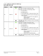
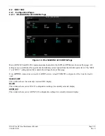
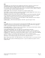
LGHT BUS AC:
Shows the input value of the AC lighting bus, if enabled.
Disregard number if it is not used in
the installation.
LGHT BUS DC:
Shows the input value of the DC lighting bus, if enabled.
Disregard number if not used in the
installation.
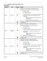
POWER (1.3V, 2.5V, 3.3V, 28 V 1/2):
Shows power input voltages of various internal components. Should be
within 10% of the desired voltage. (Example: for 2.5V field, 2500 = 2.500 Vdc; for 28V Field, 3633 = 36.33
Vdc).
Replace the display if these values are more than 10% from the desired voltage.
INTRNL TEMP 1, 2:
Shows the internal temperature sensor values of the display, in degrees Celsius. (Example:
45267 = 45.267°C)
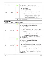
DISCRETE
SYS ID 1, 2, 3:
Shows the current system ID assigned to the display. Green indicates that the System ID pin is
strapped to ground. Black indicates that the System ID pin is left ‘open’ and not strapped to ground. PFD #2 is
not used in SEP aircraft.
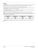
GDU System ID 1
GDU System ID 2
GDU System ID 3
Display Mode
Black Black Green MFD
Black Black Black
PFD
#1
Green Black Black PFD
#2
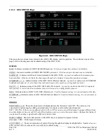
RVRSNRY MODE 1, 2:
Shows the current status of the reversionary modes.
Reversionary Mode 1 is activated by
the GMA 1347 reversion button. Reversionary Mode 2 is activated by a second GMA 1347, if installed.
Reversionary 1 input is a ground on Pin 58, reversionary 2 input is a ground on Pin 15.
SPARE INPUT:
A green box indicates Pin 14 is grounded.
This input should have a black box, if it is green
check for connector miswiring or a bent pin.
TEST/DEMO MODE SLCT:
A green box indicates Pin 53/54 is grounded.
These inputs should have a black
box, if either box is green check for connector miswiring or a bent pin.
PULSE PER SEC 1, 2:
Shows status of GPS time synchronization inputs (from GIA) to the GDU.
Used for
Garmin testing, not useful for troubleshooting.
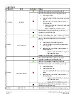
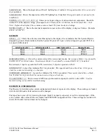
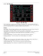
DISCRETE IN CONFIGURATION
The Discrete In field shows the current configuration of discrete inputs into the display. These settings are loaded
with the G1000 Loader Card and must not be changed.
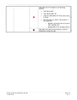
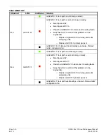
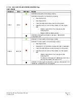
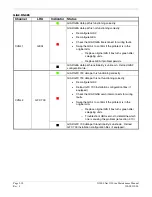
The input box is green if it is receiving the input, black if no input is expected, or red for a missing input. If the
active column does not match the set column, load PFD/MFD configuration files. These settings are loaded with
the G1000 Loader Card and must not be changed.
Содержание G1000 NAV III
Страница 1: ...190 00352 00 March 2008 Rev L G1000 NAV III LINE MAINTENANCE MANUAL ...
Страница 28: ...Page 1 18 G1000 Nav III Line Maintenance Manual Rev L 190 00352 00 Blank Page ...
Страница 120: ...Page 2 92 G1000 Nav III Line Maintenance Manual Rev L 190 00352 00 Blank Page ...
Страница 178: ...Page 5 4 G1000 Nav III Line Maintenance Manual Rev L 190 00352 00 This page intentionally left blank ...
Страница 184: ...Page 6 6 G1000 Nav III Line Maintenance Manual Rev L 190 00352 00 Blank Page ...
Страница 248: ...Page B 34 G1000 Nav III Line Maintenance Manual Rev L 190 00352 00 Blank Page ...

