13-18-609 Page 52
5-6
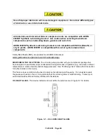
Figure 5- 3 – THERMOSTATIC OIL MIXING VALVE
Normal Package Operation -
The AirSmart controller includes an algorithm that determines, in real time,
and on the basis of the intake temperature and the programmed target discharge pressure, the minimum
discharge temperature the compressor must attain in order to keep water vapor from condensing in the oil
system. Signals from the controller command the 3-way ball valve servo to rotate and mix hot and cold oil
streams until the desired compressor discharge temperature is achieved. Refer to Figure 5-4 for the dew
point trends of the compressed air at four typical pressure levels.
At startup, the mixing valve is on full bypass mode. As system heat load increases with ambient
temperature or load, the mixing valve sends more oil flow to the cooler to maintain adequate compressor
discharge temperature.
While the mixing valve is in its modulating range (between extremes of valve position), a compressor
discharge temperature deviation exc/- 10
°
F from the calculated value will trigger an alarm display
to caution that a system malfunction is taking place. Note that the alarm is not triggered once the valve
has reached either end-of-travel position, as oil mixing no longer controls the compressor discharge
temperature.
Low Air Demand and Package Operation
– During periods of very low air demand, such as when the
package is operated in short cycles, the oil system may not reach a high enough temperature to keep
water vapor from condensing, in spite of the oil mixing valve bypassing all flow around the heat
exchanger.
Under these conditions, it is recommended that the package operation be prolonged after each unload
condition is achieved - this can be easily accomplished by adjusting the
“Auto Timer” option in the
AirSmart controller. Refer to the AirSmart controller user
’s manual 13-17-600 for detailed programming
instructions of this parameter and adjust the
“Auto Timer” parameter to a value of at least 5 minutes.
Содержание VS80A
Страница 31: ...13 18 609 Page 30 4 5 Figure 4 2 PIPING AND INSTRUMENTATION ILLUSTRATION 300CGE797 A Ref Drawing...
Страница 33: ...13 18 609 Page 32 4 7 300CGE546 04 Ref Drawing Page 2 of 4...
Страница 34: ...13 18 609 Page 33 4 8 300CGE546 04 Ref Drawing Page 3 of 4...
Страница 35: ...13 18 609 Page 34 4 9 300CGE546 04 Ref Drawing Page 4 of 4...
Страница 37: ...13 18 609 Page 36 4 11 301CGE546 B Ref Drawing Page 2 of 4...
Страница 38: ...13 18 609 Page 37 4 12 301CGE546 B Ref Drawing Page 3 of 4...
Страница 39: ...13 18 609 Page 38 4 13 301CGE546 B Ref Drawing Page 4 of 4...
Страница 41: ...13 18 609 Page 40 4 15 302CGE546 05 Ref Drawing Page 2 of 4...
Страница 42: ...13 18 609 Page 41 4 16 302CGE546 05 Ref Drawing Page 3 of 4...
Страница 43: ...13 18 609 Page 42 4 17 302CGE546 05 Ref Drawing Page 4 of 4...
Страница 45: ...13 18 609 Page 44 4 19 303CGE546 B Ref Drawing Page 2 of 4...
Страница 46: ...13 18 609 Page 45 4 20 303CGE546 B Ref Drawing Page 3 of 4...
Страница 47: ...13 18 609 Page 46 4 21 303CGE546 B Ref Drawing Page 4 of 4...
Страница 70: ...13 18 609 Page 69 9 2 Figure 9 1 MINIMUM DISCHARGE PRESSURE CHECK VALVE...
Страница 86: ...NOTES...
Страница 87: ...NOTES...


