13-18-610 Page 76
14-1
SECTION 14
MAINTENANCE SCHEDULE
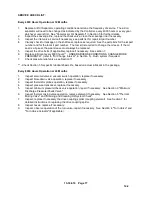
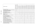
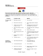
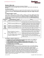
SERVICE CHECK LIST
Air Filter)
– Operating conditions determine frequency of service. See “Air Filter”, Section 7.
Package Inlet Filters – Operating conditions determine frequency of service
. See
“Air Filter”,
Section 7.
Motor Lubrication
– See “Installation”, Section 2.
Every 8 Hours Operation
1.
Check air/oil reservoir oil level, add oil if required. See Section 5 for information. If oil consumption
is high, refer to Section 15, Excessive Oil Consumption. DO NOT MIX LUBRICANTS.
2.
Check operation of the machine, proper loading and unloading.
3.
Check discharge pressure and temperature.
4.
Check control panel for advisory text messages.
Every 125 Hours Operation
1.
Check for dirt accumulation on oil/aftercooler core faces and the cooling fan. If cleaning is required,
clean the exterior fin surfaces of the cores by blowing compressed air carrying a nonflammable
safety solvent, which will not damage aluminum, in a direction opposite that of the cooling air flow.
The cleaning operation will keep the exterior cooling surfaces clean and ensure effective heat
dissipation.
Every 1000 Hours Operation Or 3 Months
1.
Replace the oil filter element, as indicated by the AirSmart Controller, every 1000 hours or every
3 months, whichever occurs first. See
“Oil Filter”, Section 5.
2.
Clean or replace the control box filter (if applicable), as indicated by the Air Smart Controller, ever
1000 hours or every 3 months, whichever occurs first.
Every 2000 Hours Operation Or 6 Months
1.
Replace air filter element, operating conditions determine the frequency of service. The
air filter will need to be changed, as indicated by the Controller, every 2000 hours or
every 6 months, whichever occurs first. See "Air Filter", Section 7.
2.
Collect oil sample and send to the GD oil lab.
3.
Replace package enclosure filter pad (if applicable.)
Every 3000 Hours Operation Or 9 Months
1.
Inspect the motor bearings, re-grease if necessary, see Section 2.
Содержание VS80A
Страница 31: ...13 18 609 Page 30 4 5 Figure 4 2 PIPING AND INSTRUMENTATION ILLUSTRATION 300CGE797 A Ref Drawing...
Страница 33: ...13 18 609 Page 32 4 7 300CGE546 04 Ref Drawing Page 2 of 4...
Страница 34: ...13 18 609 Page 33 4 8 300CGE546 04 Ref Drawing Page 3 of 4...
Страница 35: ...13 18 609 Page 34 4 9 300CGE546 04 Ref Drawing Page 4 of 4...
Страница 37: ...13 18 609 Page 36 4 11 301CGE546 B Ref Drawing Page 2 of 4...
Страница 38: ...13 18 609 Page 37 4 12 301CGE546 B Ref Drawing Page 3 of 4...
Страница 39: ...13 18 609 Page 38 4 13 301CGE546 B Ref Drawing Page 4 of 4...
Страница 41: ...13 18 609 Page 40 4 15 302CGE546 05 Ref Drawing Page 2 of 4...
Страница 42: ...13 18 609 Page 41 4 16 302CGE546 05 Ref Drawing Page 3 of 4...
Страница 43: ...13 18 609 Page 42 4 17 302CGE546 05 Ref Drawing Page 4 of 4...
Страница 45: ...13 18 609 Page 44 4 19 303CGE546 B Ref Drawing Page 2 of 4...
Страница 46: ...13 18 609 Page 45 4 20 303CGE546 B Ref Drawing Page 3 of 4...
Страница 47: ...13 18 609 Page 46 4 21 303CGE546 B Ref Drawing Page 4 of 4...
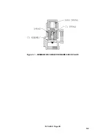
Страница 70: ...13 18 609 Page 69 9 2 Figure 9 1 MINIMUM DISCHARGE PRESSURE CHECK VALVE...
Страница 86: ...NOTES...
Страница 87: ...NOTES...


