13-18-609 Page 82
15-3
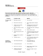
SYMPTOM
POSSIBLE CAUSE
REMEDY
Excessive oil
consumption
1.
Oil separation malfunction
1.
See
“Oil Carryover” in this section.
2.
Oil leaks at fittings and gaskets
2.
Detect and correct oil leaks.
3.
Shaft seal leaking
3.
Inspect or replace shaft seal.
High discharge
air, oil
Temperature
(air, water
cooled cores)
1.
Oil mixing valve stuck on bypass
mode
1.
Check 24Vdc power feed to servo.
Check ModBus connection to servo.
Check servo-to-valve coupling.
Check rotation of ball valve.
2.
Clogged oil filter
2.
Inspect and replace filter.
3.
Clogged cooler (interior)
3.
Inspect and clear cooler.
4.
Clogged oil lines
4.
Inspect and clear oil lines.
5.
Low oil level
5.
Add oil to proper level.
High discharge
air, oil
Temperature
(air cooled
cores)
1.
Dirty or clogged cooler outer
surfaces.
1.
Inspect and clean cooler outer
surfaces.
2.
Insufficient cooling air flow
2.
Verify (ductwork) back pressure does
not exceed .1
” water gauge.
High discharge
air, oil
Temperature
(water cooled
cores)
1.
Optional water temp regulating or
shut-off valve malfunction
1.
Refer to Section 6, Page 56
“Heat
Exchangers
” for details.
2.
Insufficient cooling water flow
2
See Section 6, Page 56 for details on
adequate cooling water flow rates.
VFD Shutdown
on Overheat
1.
Ambient temperature exceeds
45
°
C
1.
Check location ventilation and
improve if necessary.
2.
VFD air filters dirty
2.
Inspect, clean or replace elements.
Содержание VS80A
Страница 31: ...13 18 609 Page 30 4 5 Figure 4 2 PIPING AND INSTRUMENTATION ILLUSTRATION 300CGE797 A Ref Drawing...
Страница 33: ...13 18 609 Page 32 4 7 300CGE546 04 Ref Drawing Page 2 of 4...
Страница 34: ...13 18 609 Page 33 4 8 300CGE546 04 Ref Drawing Page 3 of 4...
Страница 35: ...13 18 609 Page 34 4 9 300CGE546 04 Ref Drawing Page 4 of 4...
Страница 37: ...13 18 609 Page 36 4 11 301CGE546 B Ref Drawing Page 2 of 4...
Страница 38: ...13 18 609 Page 37 4 12 301CGE546 B Ref Drawing Page 3 of 4...
Страница 39: ...13 18 609 Page 38 4 13 301CGE546 B Ref Drawing Page 4 of 4...
Страница 41: ...13 18 609 Page 40 4 15 302CGE546 05 Ref Drawing Page 2 of 4...
Страница 42: ...13 18 609 Page 41 4 16 302CGE546 05 Ref Drawing Page 3 of 4...
Страница 43: ...13 18 609 Page 42 4 17 302CGE546 05 Ref Drawing Page 4 of 4...
Страница 45: ...13 18 609 Page 44 4 19 303CGE546 B Ref Drawing Page 2 of 4...
Страница 46: ...13 18 609 Page 45 4 20 303CGE546 B Ref Drawing Page 3 of 4...
Страница 47: ...13 18 609 Page 46 4 21 303CGE546 B Ref Drawing Page 4 of 4...
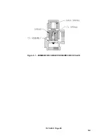
Страница 70: ...13 18 609 Page 69 9 2 Figure 9 1 MINIMUM DISCHARGE PRESSURE CHECK VALVE...
Страница 86: ...NOTES...
Страница 87: ...NOTES...


