13-10-615 Page 32
Solenoid Valves TVC and TVO
- These valves control position of the turn valve in response to signals
from the “AutoSentry” controller. With both valves de-energized, equal pressure is supplied to both sides
of the actuator to hold it in its current position. If TVC only is energized, the right side of the turn valve
actuator is exhausted to the compressor inlet cavity, causing the turn valve to move towards the full load
position. If TVO only is energized, the left side of the turn valve actuator is exhausted to the compressor
inlet cavity, causing the turn valve to move towards the unload position.
System Pressure Transducer
- This transducer is connected after the minimum pressure valve. It
converts the pressure in the plant air system into an electrical signal for use by the “AutoSentry” controller
for modulation and control.
Reservoir Pressure Transducer
- This transducer is connected to the coolant system. Its signal is used
to prevent loaded starts, monitor oil pressure, and monitor the condition of the separator.
Air Filter Vacuum Switch
- This switch is used to monitor air filter condition and alert the user if the filter
requires service or replacement.
Discharge Thermistor
- This sensor is located directly in the compressor discharge. Its signal is used to
monitor compressor temperature and shut down the compressor if a coolant problem is detected.
Reservoir Thermistor
- This sensor is located in the reservoir / separator housing and is used to monitor
temperature and shutdown the compressor if temperature problems occur at the separator.
Emergency Stop Pushbutton
- This is a maintained pushbutton, and removes power from the controller
outputs regardless of controller status. It is located on the upper section of the panel, next to the keypad.
This should be used for emergency purposes only - use the keypad [STOP/RESET] for normal controlled
stopping.
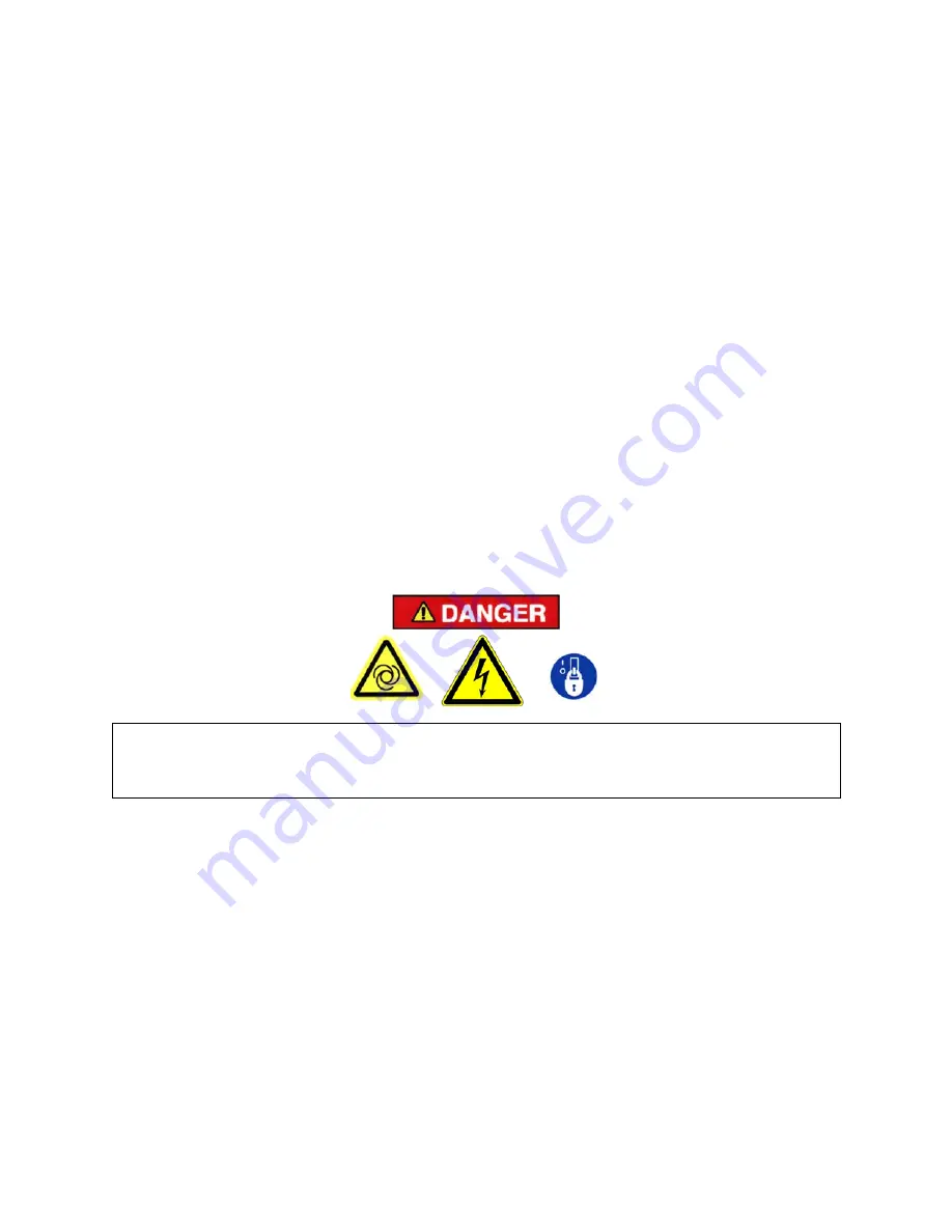
Automatic restarting or electrical shock can cause injury or death. Open,
lockout and tagout main disconnect and any other circuits before servicing
unit.
Control Transformer
- This changes the incoming power voltage to 110-120 volts for use by all unit
control devices. Two primary fuses and one secondary fuse are provided. Refer to adjacent labeling for
replacement information.
Terminal Strip
- This provides connections for all 110-120 volt devices not contained within the
enclosure.
Fan Starter
- The starter is used to provide control and overload protection for the fan. Overload heaters
should be selected and adjusted based on the motor nameplate amps and the instructions located inside
the cover of the electrical enclosure. The starter must be present even for packages without a local fan.
Main Starter
- This starter is used to provide control and overload protection for the main drive motor.
Full voltage starters employ a single contactor; overload heaters should be selected and adjusted based
on the motor nameplate amps and the instructions located inside the cover of the enclosure. Wye-delta
starters employ three contactors which are controlled sequentially to provide low current starting. For
Wye-delta starters, the motor nameplate amps must be first multiplied by 0.577 before using the heater
table.
Содержание AUTO SENTRY EAU99P
Страница 13: ...13 10 615 Page 12 Figure 1 6 PACKAGE AIR OIL FLOW DIAGRAM 202EDM797 Ref Drawing ...
Страница 35: ...13 10 615 Page 34 Figure 4 7 CONTROL SCHEMATIC COMPRESSOR AT FULL LOAD 206EAU797 B Ref Drawing ...
Страница 38: ...13 10 615 Page 37 Figure 4 10 WIRING DIAGRAM WYE DELTA ES CONTROLLER AIR COOLED 202EAU546 D Ref Drawing ...
Страница 40: ...13 10 615 Page 39 205EAU546 D Ref Drawing Page 2 of 2 ...
Страница 44: ...13 10 615 Page 43 Figure 5 3 FLOW DIAGRAM 210EAU797 B Ref Drawing ...


