GARDEN WAY 12194 Скачать руководство пользователя страница 8

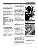
STEP 4: Attach Forward 
Clutch Rod

1.  The upper end of the Forward Clutch
rod is attached to the bottom of the han-
dlebar control panel.  Turn the rod (L,
Figure 2-7) so that the small bend at its
lower end points inward toward the clutch
swivel plate (HH).

2.  Insert a hairpin cotter down through
the hole in the rod that is located closest
to the bend (see Figure 2-7).  

3.  There are four numbered holes in the
clutch swivel plate (see Figure 2-8) and
four numbered slots in the curved height
adjustment bracket.  For correct operation
of the Forward Clutch rod, the numbered
hole used for the Forward Clutch rod must
match with the numbered slot in the
height adjustment bracket.  For example,
if the handlebar is set in slot #1, then the
Forward Clutch rod must be installed in
hole #1 of the clutch swivel plate.

IMPORTANT:  Whenever the handlebar
height is changed, the hole position of the
Forward Clutch rod must be changed
accordingly.  Changing the handlebar
height changes the tension on the
Forward Clutch rod – this tension must be
adjusted by relocating the rod in the
appropriate hole in the clutch swivel plate.

4.  Select the proper hole in the clutch
swivel plate and insert the Forward Clutch
rod so that the tip faces inward (see
Figure 2-8).  Secure the rod by inserting a
second hairpin cotter through the hole
near the tip of the rod.

5.  Check for correct tension on the
Forward Clutch rod as follows:

(a) There are two interconnected Forward

Clutch paddles that hang beneath the
control panel.  Lift and hold the right-
side paddle against the handlebar grip.

(b) While squeezing the paddle, measure

the gap between the E-ring and the
lower end of the clutch rod bracket
(see Figure 2-9).  The gap should be
3/16"-to-5/16".  NOTE: A stack of five
pennies is approximately 5/16" thick.

(c) If the gap is incorrect:

(1) First check that the Forward Clutch

rod is in the correct hole in the
clutch swivel plate.  If not, reposi-
tion the rod and repeat Step 5b.

(2) If the Forward Clutch rod is in the

correct hole and the gap is incor-
rect, you will need to adjust the
length of the Forward Clutch rod.
To do this, first release the
Forward Clutch paddle and then
disconnect the rod from the clutch
swivel plate (remove hairpin cotter
at end of rod and pull rod out of
hole in clutch swivel plate). 

If the gap is more than 5/16", rotate
the rod counterclockwise (as
viewed from the front of tiller) to
decrease the gap.  Reinstall the rod
in the correct clutch swivel plate
hole, secure it with the hairpin
cotter, and repeat Steps 5a and 5b. 

If the gap is less than 3/16", rotate
the rod clockwise (as viewed from
the front of tiller) to increase the
gap.  Reinstall the rod in the correct
clutch swivel plate hole, secure it
with the hairpin cotter, and repeat
Steps 5a and 5b. 

8

Section 2:  Assembly

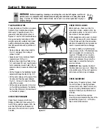
Figure 2-7: Install Forward Clutch rod.

L

HH

Hairpin Cotter

Figure 2-8: Numbered settings for handlebar
height slots and clutch swivel plate holes.

Figure 2-9: While squeezing Forward Clutch
paddle, measure gap between end of
bracket and E-ring.

Gap should be

3/16"-to-5/16" 

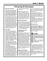
STEP 5: Check Gear Oil Level in
Transmission

The transmission was filled with gear oil at
the factory.  However, you should check
the gear oil level to make certain it is
correct.

IMPORTANT: Do not operate the tiller if
the gear oil level is low.  Doing so will
result in severe damage to the transmis-
sion components.

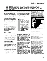
1.  Move the tiller to a level area.

2.  Pull the Depth Regulator Lever (M,
Figure 2-10) straight back and then slide it
to the second notch from the top.  If the
lever does not move freely, lift the tine
hood flap and look for a plastic tie secur-
ing the lever in place.  Cut and remove the
tie.

SERIA

L NU

MBER

1

3

2

4

2

3

4

1

Содержание 12194

Страница 1: ...Model 12194 Owner s Manual 8HP Model Tiller Safety Assembly Controls Operation Maintenance GARDEN WAY INCORPORATED...

Страница 2: ...Back Cover Dear Owner Thank you for purchasing our product You now own one of the finest rear tine rototillers available It has been designed engineered and manufactured to give you the best possible...

Страница 3: ...any source of ignition until fuel vapors have dissipated 7 Never make adjustments when engine is running unless recommended by manufacturer Operation 1 Do not put hands or feet near or under rotating...

Страница 4: ...slope that is too steep for safety When on slopes slow down and make sure you have good footing Never permit the tiller to freewheel down slopes 18 Never allow bystanders near the unit 19 Only use at...

Страница 5: ...ING TINES OR MAKING REPAIRS KEEP BYSTANDERS AWAY FROM MACHINE KEEP AWAY FROM ROTATING PARTS USE EXTREME CAUTION WHEN REVERSING OR PULLING THE MACHINE TOWARDS YOU WARNING Operating Symbols Various symb...

Страница 6: ...mbly steps 3 Remove the handlebar assembly from the carton Do not remove the two control levers from the handlebars 4 Remove the separate hardware bag from the carton Check that you have the items lis...

Страница 7: ...the mounting tabs Figure 2 3 6 To remove the tiller from its shipping platform first carefully unwrap the Wheel Gear Lever and cable assembly G Figure 2 5 from around the engine Next move the lever to...

Страница 8: ...e pennies is approximately 5 16 thick c If the gap is incorrect 1 First check that the Forward Clutch rod is in the correct hole in the clutch swivel plate If not reposi tion the rod and repeat Step 5...

Страница 9: ...pping purposes the engine throttle cable assembly is wrapped around the engine Carefully unwrap the cable and attach it as follows 1 Route the throttle cable up the right side handlebar and insert the...

Страница 10: ...d to tap the knob down until it seats firmly on the lever see Figure 2 15 5 Secure the cable to the left side han dlebar with two plastic ties T Figure 2 14 located about two feet apart Snip off any e...

Страница 11: ...e DISENGAGE position Forward Clutch The two interconnected levers B Figure 3 2 control the engagement of forward drive to the wheels and power to the tines To Operate the Forward Clutch 1 Before engag...

Страница 12: ...r in ENGAGE see WARNING statement on previous page 2 Release the Forward Clutch Levers 3 To move the tiller in reverse first stop all forward motion Then lift up the han dlebars until the tines clear...

Страница 13: ...clutch swivel plate and insert the Forward Clutch rod tip faces inward Secure the rod with the hairpin cotter d Check for correct tension on the Forward Clutch rod as described in item 5 of Step 4 Att...

Страница 14: ...after first 2 hours of operation 4 Check transmission gear oil level after first 2 hours of operation STARTING AND STOPPING THE ENGINE Pre Start Checklist Make the following checks and perform the fo...

Страница 15: ...iques in this Section before you actually put the tines into the soil 1 Follow the Pre Start Checklist on the previous page Be sure that the Wheel Gear Lever is in the ENGAGE position 2 Put the Depth...

Страница 16: ...ne 1 To stop the wheels and tines release the Forward Clutch paddles or the Reverse Clutch Lever whichever is engaged 2 To stop the engine move the Engine Throttle Lever to STOP Turning the Tiller Aro...

Страница 17: ...of the unit to avoid making foot prints in your freshly tilled or cultivated soil Footprints cause soil compaction that can hamper root penetration and contribute to soil erosion They can also plant...

Страница 18: ...re the load Use sturdy ramps and manually engine shut off roll the tiller into and out of the vehicle Two or more people are needed to do this Ramps must be strong enough to support the combined weigh...

Страница 19: ...it with the two nuts 8 Put Wheel Gear Lever in ENGAGE and reconnect spark plug wire before attempt ing to start the engine To Change from High to Low Speed 1 Stop the engine allow it to cool and disc...

Страница 20: ...tines for wear Check air pressure in tires Service spark plug Change more frequently in dusty or dirty conditions Change after first 2 hours of break in operation Check after first 2 hours of break i...

Страница 21: ...LEAKS Before each use check your tiller for signs of an oil leak usually a dirty oily accumulation either on the unit or on the floor where it has been parked A little seepage around a cover or oil se...

Страница 22: ...on the side of the transmission 8 Securely reinstall the oil level check plug 9 Securely reinstall the gear oil fill plug on top of the transmission 10 Remove the prop and reinstall the wheel ENGINE O...

Страница 23: ...JUSTMENT When the Wheel Gear Lever is in DISEN GAGE the wheels will roll freely free wheel The wheels should not roll freely when the lever is in ENGAGE If the wheels roll freely when the Wheel Gear L...

Страница 24: ...tine shaft before reinstalling the tine assem blies Tighten the hardware very securely Removing and Installing Individual Tines 1 Use two 9 16 box end wrenches to remove the two bolts C Figure 5 7 an...

Страница 25: ...e pulling the engine starter rope with your right hand 6 On the left side of the unit as viewed from operator s position remove the hairpin cotter from the clevis pin F Figure 5 11 that connects the f...

Страница 26: ...t not the opera tor s position If the belt tension is correct reinstall the belt cover and secure it with the two nuts If the guide mark is aligned with the guide pin or moves to the right side of the...

Страница 27: ...ey C Figure 5 16 by moving it to the front of the pulley 5 Pull the forward drive belt up and off the pulleys by feeding the bottom half of the belt in between the engine and trans mission pulleys B I...

Страница 28: ...the reverse belt downward to create slack in the belt Then reach underneath the transmission and slip the belt off the front of the trans mission pulley B Figure 5 18 5 Pull the belt up and past the e...

Страница 29: ...e overheats 1 Engine cooling system clogged 1 Clean air cooling area see Engine Owner s Manual 2 Carburetor out of adjustment 2 See Engine Service Dealer 3 Oil level is low 3 Check oil level see Engin...

Страница 30: ...lebars in lowest setting 69 TILLER WIDTH Hood Width 22 Tilling Width 20 Wheel Width 18 1 2 Handlebar Width 20 1 4 TILLER WEIGHT Approximate Weight without oil or gas 204 lbs TRANSMISSION GEAR OIL SPEC...

Страница 31: ...31 NOTES...

Страница 32: ...y specified replacement parts are available from your authorized dealer or directly from the factory For parts order ing information refer to the parts catalog Engine Service and Repair For engine ser...

Страница 33: ...33...

Отзывы: