


19
Section 4: Operation
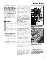
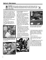
CHANGING BELT RANGE SPEEDS
The tiller has two forward belt range
speeds for the wheels and tines: Low and
High. The two ranges are obtained by
moving the forward drive belt between
two sets of grooves on the forward drive
pulley and the transmission drive pulley.
NOTE: The High speed belt range is rec-
ommended for all tilling purposes. The
Low speed belt range will operate the
tines and wheels at a slower forward
speed, which may be suitable in some
conditions (such as tilling in very hard
ground).
To Change from Low to High Speed:
1. Stop the engine, allow it to cool, and
disconnect the spark plug wire.
2. Put Wheel Gear Lever in DISENGAGE.
3. Remove the two nuts from the plastic
belt cover on top of the transmission and
remove the belt cover.
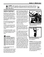
4. From beneath the tiller, move the
forward drive belt out of the transmission
low speed groove (B, Figure 4-10) and
into the high speed groove (D).
5. Pull upward on the belt to remove any
slack and slip the belt out of the engine
drive pulley low speed groove (A, Figure
4-10) and into the high speed groove (C).
NOTE: If the belt is difficult to move, pull
on the engine start rope while pushing the
belt with your finger (engine drive pulley
will turn as start rope is pulled).
6. Check that the belt is within the forward
belt guide (E, Figures 4-10 and 4-11) on
the right-side of the unit and is within the
forward idler (F, Figure 4-11) on the left-
side. Be sure that the belt is situated in
the center grooves (C and D, Figure 4-10)
of the engine (upper) and transmission
(lower) pulleys.
7. Reinstall the plastic belt cover and
secure it with the two nuts.
8. Put Wheel Gear Lever in ENGAGE and
reconnect spark plug wire before attempt-
ing to start the engine.
To Change from High to Low Speed:
1. Stop the engine, allow it to cool, and
disconnect the spark plug wire.
2. Put Wheel Gear Lever in DISENGAGE.
3. Remove the two nuts from the plastic
belt cover on top of the transmission and
remove the belt cover.
4. From beneath the tiller, move the
forward drive belt out of the transmission
pulley high speed groove (D, Figure 4-10)
and into the low speed groove (B).
5. Pull upward on the belt to remove any
slack and slip the belt out of the engine
drive pulley high speed groove (C, Figure
4-10) and into the low speed groove (A).
NOTE: If the belt is difficult to move, pull
on the engine start rope while pushing the
belt with your finger (engine drive pulley
will turn as start rope is pulled).
6. Check that the belt is within the forward
belt guide (E, Figures 4-10 and 4-11) on
the right-side of the unit and is within the
forward idler (F, Figure 4-11) on the left-
side. Be sure that the belt is situated in
the rear grooves (A and B, Figure 4-10) of
the engine (upper) and transmission
(lower) pulleys.
7. Reinstall the plastic belt cover and
secure it with the two nuts.
8. Put the Wheel Gear Lever in ENGAGE
and reconnect the spark plug wire before
attempting to start the engine.
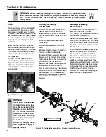
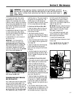
Figure 4-11: Top view of forward drive
pulley system (engine is at left-side of
view).
Figure 4-10: Right-side view of engine and
transmission pulleys (engine is at right-
side of view).
WARNING
Before changing belt speeds,
stop engine, wait for all parts
to stop moving, let engine
cool and disconnect spark
plug wire.
Failure to follow these
instructions could result in
personal injury.
Reverse
Belt
Reverse
Idler
E
A
(Low)
B
(Low)
C
(High)
D
(High)
(Low)
(High)
F
E
Engine
Engine
Содержание 12194
Страница 31: ...31 NOTES...
Страница 33: ...33...


