


12
Section 3: Features and Controls
IMPORTANT: The Forward Clutch Levers
are connected to a mechanical interlock
that automatically shifts the separate
Wheel Gear Lever (A, Figure 3-1) into the
ENGAGE position when either of the
Forward Clutch Levers is lifted up against
the handlebars. This is a safety feature
designed to prevent the wheels from
being in the DISENGAGE (freewheel) posi-
tion when the tines are rotating.
Before starting the engine, test the func-
tion of the mechanical interlock as
follows:
1. Put the Wheel Gear Lever in the DISEN-
GAGE position and roll the tiller back and
forth a few inches. The wheels should roll
freely.
2. Without rolling the tiller, squeeze either
of the Forward Clutch Levers (“paddles”)
against the handlebar grips. As the levers
move upward, the mechanical interlock
will automatically move the Wheel Gear
Lever forward into the ENGAGE position
(roll the tiller back and forth a few
inches). If it does, the wheels will not roll
freely when you push and pull on the han-
dlebars.
3. The mechanical interlock is working
properly if it functioned as described in
Step 2. If the mechanical interlock did not
function properly, do not operate the tiller
until it has been inspected and corrected
(see your authorized dealer or contact the
factory).
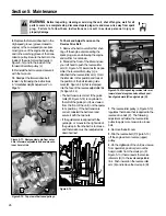
Reverse Clutch
This lever (C, Figure 3-3) controls the
engagement of reverse drive to the wheels
and power to the tines. It is used for
short distances and is the only control
that provides reverse direction of the
wheels.
To Operate the Reverse Clutch:
1. Before engaging the Reverse Clutch,
put the Wheel Gear Lever in ENGAGE (see
“WARNING” statement on previous page).
2. Release the Forward Clutch Levers.
3. To move the tiller in reverse, first stop
all forward motion. Then lift up the han-
dlebars until the tines clear the ground
and pull the Reverse Clutch lever out. The
wheels will rotate in a reverse direction as
long as the lever is held in REVERSE. To
stop the wheels and tines, release the
lever and it will return to NEUTRAL.
Never attempt to till while going in the
reverse direction.
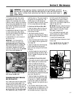
Depth Regulator
This lever (D, Figure 3-4) controls the
tilling depth of the tines. Pull the lever
straight back and slide it up or down to
engage the notched height settings.
The highest notch (lever all the way
down) raises the tines approximately
1-1/2 inches off the ground. This “travel”
position allows the tiller to be moved
without the tines digging into the ground.
Moving the lever up increases the tilling
depth. The lowest notch allows a tilling
depth of approximately six to eight
inches, depending on soil conditions.
For best results, always begin tilling at a
very shallow depth setting and gradually
increase the tilling depth. Complete
details on using the Depth Regulator are
found in the “Operation” Section of this
manual.
WARNING
• Use extreme caution when
reversing or pulling the
machine towards you. Look
behind to avoid obstacles.
• Never attempt to till in
reverse.
Failure to follow this warning
could result in personal injury
or property damage.
Figure 3-3: Reverse Clutch lever.
C
WARNING
Always place the Depth Regu-
lator Lever in the “travel”
position before starting the
engine. This position pre-
vents the tines from touching
the ground until you are ready
to begin tilling.
Failure to follow this warning
could result in personal injury
or property damage.
Figure 3-4: Depth Regulator Lever.
D
Содержание 12194
Страница 31: ...31 NOTES...
Страница 33: ...33...


