


11
TILLER FEATURES
AND CONTROLS
This section describes the location and
function of the controls on your tiller.
Refer to the following section “Operation”
for detailed operating instructions.
Practice using these controls, with the
engine shut off, until you understand the
operation of the controls and feel confi-
dent with each of them.
IMPORTANT: Refer to the separate engine
manufacturer’s Engine Owner’s Manual
for information about the controls on the
engine.
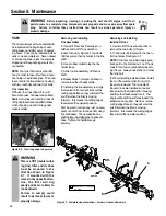
Wheel Gear Lever
This lever (A, Figure 3-1) has two posi-
tions: ENGAGE and DISENGAGE.
In the ENGAGE position, the wheels will
start turning when either the Forward
Clutch or the Reverse Clutch is engaged
(the tines will also start turning when
either clutch is engaged).
The DISENGAGE position places the
wheels in the freewheeling mode to allow
the unit to be moved without the engine
running. Use the DISENGAGE position
only when the engine is not running. See
“DANGER” statement that follows.
To shift to ENGAGE, gently (do not force)
move the lever forward while also rolling
the tiller a few inches forward or back-
ward. (Moving the tiller helps to align the
shift mechanism with the transmission
wheel drive gears.) The wheels will not
freewheel when the lever is properly set in
the ENGAGE position.
To shift to DISENGAGE (freewheel)
simply move the lever rearward, without
rolling the tiller. The wheels will roll
freely when the lever is properly set in the
DISENGAGE position.
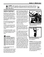
Forward Clutch
The two interconnected levers (B, Figure
3-2) control the engagement of forward
drive to the wheels and power to the tines.
To Operate the Forward Clutch:
1. Before engaging the Forward Clutch,
put the Wheel Gear Lever in the ENGAGE
position (see “WARNING” below).
2. Lift and hold one or both of the levers
against the handlebar grips to engage the
wheels and tines.
3. Release BOTH levers to disengage the
wheels and tines. All forward motion will
stop (the engine will continue to run).
DANGER
Never place the Wheel Gear
Lever in DISENGAGE (Free-
wheel) when the engine is
running.
Having the Wheel Gear Lever
in DISENGAGE and then
engaging the tines/wheels
with either the Forward Clutch
or the Reverse Clutch could
allow the tines to propel the
tiller rapidly backward.
Failure to follow this instruc-
tion could result in personal
injury or property damage.
WARNING
Before operating your
machine, carefully read and
understand all safety, controls
and operating instructions in
this Manual, the separate
Engine Owner’s Manual, and
on the decals on the machine.
Failure to follow these
instructions can result in
serious personal injury.
Section
3
Features and Controls
Figure 3-1: Wheel Gear Lever.
A
Figure 3-2: Forward Clutch levers.
B
WARNING
Never engage the wheels and
tines with the Forward Clutch
or the Reverse Clutch unless
the Wheel Gear Lever is in
ENGAGE.
Engaging the Forward Clutch
or the Reverse Clutch when
the wheels are not engaged
could allow the tines to rapidly
propel the tiller backward.
Failure to follow this warning
could result in personal injury
or property damage.
Содержание 12194
Страница 31: ...31 NOTES...
Страница 33: ...33...


