GARDEN WAY 12194 Скачать руководство пользователя страница 13

13

Section 3:  Features and Controls

Handlebar Height Adjustment

The handlebar height is adjustable to four
different settings.  Set the handlebar
height to a comfortable setting, but keep
in mind that the handlebars will be lower
when the tines are engaged in the soil.

To Adjust the Handlebar Height:

1. Stop the engine, wait for all parts to
stop moving and then disconnect the
spark plug wire.

2. Loosen the two screws at the lower
ends of the handlebar. 

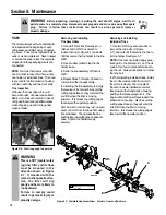
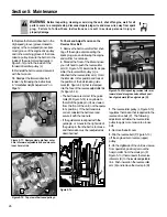
3. Loosen the height adjustment handle
(E, Figure 3-5) and pull the keyed washer
(F) free of the slots in the curved height
adjustment bracket.

4. Move the handlebars to the new slot
setting and insert the raised keys on the
keyed washer into the slot.  Tighten the
height adjustment handle securely.

5. Retighten the two screws at the ends
of the handlebar.

6. Adjust the tension on the Forward
Clutch rod shift mechanism, as follows:

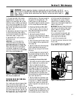
(a) Remove the inner hair pin cotter from

the end of the Forward Clutch rod.

(b) There are four numbered holes in the

clutch swivel plate (see Figure 3-6)
and four numbered slots in the curved

height adjustment bracket.  For
correct operation of the Forward
Clutch mechanism, the numbered hole
used for the Forward Clutch rod must
match the numbered slot in the height
adjustment bracket.  Example: If han-
dlebar is in slot #4, put Forward
Clutch rod in hole #4 of clutch swivel
plate.

(c) Select the correct hole in the clutch

swivel plate and insert the Forward
Clutch rod (tip faces inward).  Secure
the rod with the hairpin cotter.

(d) Check for correct tension on the

Forward Clutch rod as described in
item 5 of “Step 4: Attach Forward
Clutch Rod” on page 8.

ENGINE CONTROLS

IMPORTANT:  The engine is equipped
with either a choke control or a primer
bulb.  Refer to the engine manufacturer’s
Engine Owner’s Manual (included in the
tiller literature package) to identify which
device is on your engine.  
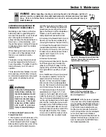
Recoil Starter

The recoil starter (G, Figure 3-7) is used
to “pull-start” the engine.

Before pulling the recoil starter handle,
make sure there are no obstacles behind
you.  See “Engine Starting and Stopping”
in the Operation Section for detailed
engine starting instructions.

Engine Throttle Lever

The throttle lever (Figure 3-8) is used to
adjust engine speed as well as stop the
engine.

Use the START position when starting the
engine.  Use the SLOW position when
idling the engine.  Pull the lever all the
way back to the STOP position to shut the
engine off.

1

3

2

4

2

3

4

1

Figure 3-6:  Handlebar height slots and
clutch swivel plate holes.

Figure 3-5

F

E

Figure 3-8:  Engine Throttle Lever.

Figure 3-7: Recoil Starter.

G

WARNING

Whenever the handlebar
height is changed, the
Forward Clutch shift mecha-
nism must be readjusted.  

When adjusting or checking
the Forward Clutch mecha-
nism, shut engine off, discon-
nect spark plug wire and
prevent it from touching the
spark plug.

Failure to follow this warning
could allow the Forward
Clutch mechanism to operate
improperly which could result
in personal injury or property
damage.

Содержание 12194

Страница 1: ...Model 12194 Owner s Manual 8HP Model Tiller Safety Assembly Controls Operation Maintenance GARDEN WAY INCORPORATED...

Страница 2: ...Back Cover Dear Owner Thank you for purchasing our product You now own one of the finest rear tine rototillers available It has been designed engineered and manufactured to give you the best possible...

Страница 3: ...any source of ignition until fuel vapors have dissipated 7 Never make adjustments when engine is running unless recommended by manufacturer Operation 1 Do not put hands or feet near or under rotating...

Страница 4: ...slope that is too steep for safety When on slopes slow down and make sure you have good footing Never permit the tiller to freewheel down slopes 18 Never allow bystanders near the unit 19 Only use at...

Страница 5: ...ING TINES OR MAKING REPAIRS KEEP BYSTANDERS AWAY FROM MACHINE KEEP AWAY FROM ROTATING PARTS USE EXTREME CAUTION WHEN REVERSING OR PULLING THE MACHINE TOWARDS YOU WARNING Operating Symbols Various symb...

Страница 6: ...mbly steps 3 Remove the handlebar assembly from the carton Do not remove the two control levers from the handlebars 4 Remove the separate hardware bag from the carton Check that you have the items lis...

Страница 7: ...the mounting tabs Figure 2 3 6 To remove the tiller from its shipping platform first carefully unwrap the Wheel Gear Lever and cable assembly G Figure 2 5 from around the engine Next move the lever to...

Страница 8: ...e pennies is approximately 5 16 thick c If the gap is incorrect 1 First check that the Forward Clutch rod is in the correct hole in the clutch swivel plate If not reposi tion the rod and repeat Step 5...

Страница 9: ...pping purposes the engine throttle cable assembly is wrapped around the engine Carefully unwrap the cable and attach it as follows 1 Route the throttle cable up the right side handlebar and insert the...

Страница 10: ...d to tap the knob down until it seats firmly on the lever see Figure 2 15 5 Secure the cable to the left side han dlebar with two plastic ties T Figure 2 14 located about two feet apart Snip off any e...

Страница 11: ...e DISENGAGE position Forward Clutch The two interconnected levers B Figure 3 2 control the engagement of forward drive to the wheels and power to the tines To Operate the Forward Clutch 1 Before engag...

Страница 12: ...r in ENGAGE see WARNING statement on previous page 2 Release the Forward Clutch Levers 3 To move the tiller in reverse first stop all forward motion Then lift up the han dlebars until the tines clear...

Страница 13: ...clutch swivel plate and insert the Forward Clutch rod tip faces inward Secure the rod with the hairpin cotter d Check for correct tension on the Forward Clutch rod as described in item 5 of Step 4 Att...

Страница 14: ...after first 2 hours of operation 4 Check transmission gear oil level after first 2 hours of operation STARTING AND STOPPING THE ENGINE Pre Start Checklist Make the following checks and perform the fo...

Страница 15: ...iques in this Section before you actually put the tines into the soil 1 Follow the Pre Start Checklist on the previous page Be sure that the Wheel Gear Lever is in the ENGAGE position 2 Put the Depth...

Страница 16: ...ne 1 To stop the wheels and tines release the Forward Clutch paddles or the Reverse Clutch Lever whichever is engaged 2 To stop the engine move the Engine Throttle Lever to STOP Turning the Tiller Aro...

Страница 17: ...of the unit to avoid making foot prints in your freshly tilled or cultivated soil Footprints cause soil compaction that can hamper root penetration and contribute to soil erosion They can also plant...

Страница 18: ...re the load Use sturdy ramps and manually engine shut off roll the tiller into and out of the vehicle Two or more people are needed to do this Ramps must be strong enough to support the combined weigh...

Страница 19: ...it with the two nuts 8 Put Wheel Gear Lever in ENGAGE and reconnect spark plug wire before attempt ing to start the engine To Change from High to Low Speed 1 Stop the engine allow it to cool and disc...

Страница 20: ...tines for wear Check air pressure in tires Service spark plug Change more frequently in dusty or dirty conditions Change after first 2 hours of break in operation Check after first 2 hours of break i...

Страница 21: ...LEAKS Before each use check your tiller for signs of an oil leak usually a dirty oily accumulation either on the unit or on the floor where it has been parked A little seepage around a cover or oil se...

Страница 22: ...on the side of the transmission 8 Securely reinstall the oil level check plug 9 Securely reinstall the gear oil fill plug on top of the transmission 10 Remove the prop and reinstall the wheel ENGINE O...

Страница 23: ...JUSTMENT When the Wheel Gear Lever is in DISEN GAGE the wheels will roll freely free wheel The wheels should not roll freely when the lever is in ENGAGE If the wheels roll freely when the Wheel Gear L...

Страница 24: ...tine shaft before reinstalling the tine assem blies Tighten the hardware very securely Removing and Installing Individual Tines 1 Use two 9 16 box end wrenches to remove the two bolts C Figure 5 7 an...

Страница 25: ...e pulling the engine starter rope with your right hand 6 On the left side of the unit as viewed from operator s position remove the hairpin cotter from the clevis pin F Figure 5 11 that connects the f...

Страница 26: ...t not the opera tor s position If the belt tension is correct reinstall the belt cover and secure it with the two nuts If the guide mark is aligned with the guide pin or moves to the right side of the...

Страница 27: ...ey C Figure 5 16 by moving it to the front of the pulley 5 Pull the forward drive belt up and off the pulleys by feeding the bottom half of the belt in between the engine and trans mission pulleys B I...

Страница 28: ...the reverse belt downward to create slack in the belt Then reach underneath the transmission and slip the belt off the front of the trans mission pulley B Figure 5 18 5 Pull the belt up and past the e...

Страница 29: ...e overheats 1 Engine cooling system clogged 1 Clean air cooling area see Engine Owner s Manual 2 Carburetor out of adjustment 2 See Engine Service Dealer 3 Oil level is low 3 Check oil level see Engin...

Страница 30: ...lebars in lowest setting 69 TILLER WIDTH Hood Width 22 Tilling Width 20 Wheel Width 18 1 2 Handlebar Width 20 1 4 TILLER WEIGHT Approximate Weight without oil or gas 204 lbs TRANSMISSION GEAR OIL SPEC...

Страница 31: ...31 NOTES...

Страница 32: ...y specified replacement parts are available from your authorized dealer or directly from the factory For parts order ing information refer to the parts catalog Engine Service and Repair For engine ser...

Страница 33: ...33...

Отзывы: