


Gamatronic Electronic Industries Ltd.
User Guide
Page 11
µ
PS Series 3:3 Phase 10kVA (GEMS)
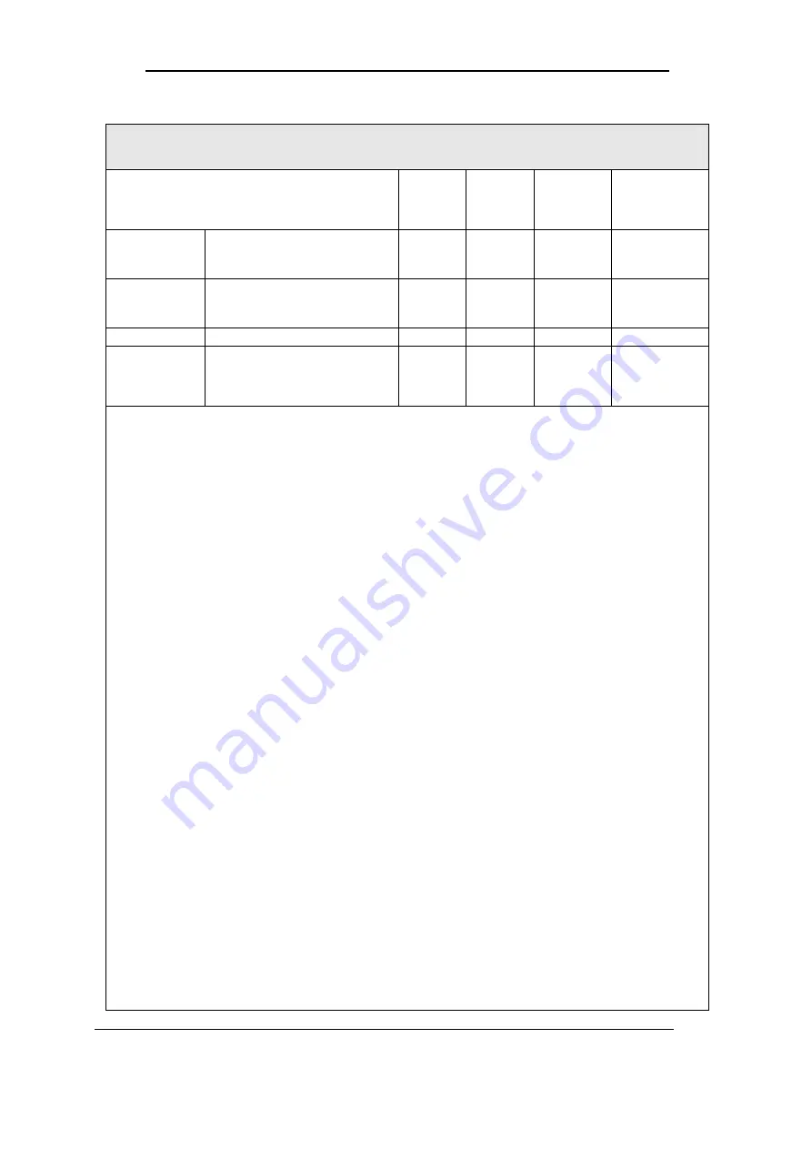
Table 2: Ratings & External Wiring Requirements
RATINGS & EXTERNAL WIRING REQUIREMENTS
µ
PS SERIES 3:3 PHASE, 10kVA, 60Hz GE MODEL
Basic unit ratings
at full load
kVA/kW
Voltage
Input
(Volts)
INPUT
CURRENT
(AMPS)
CONDUCTOR
MINIMUM
SIZE
AC INPUT
AC Input to UPS
Full Load Current 3Ø, (1)
Neutral, (1) gnd
-
208
38
(5) x 8AWG
AC OUTPUT
UPS AC Output
Full Load Current 3Ø, (1)
Neutral, (1) gnd
10/8
208
27.8
(5) x 10AWG
PE GND
- - - 4AWG
EPO
EMERGENCY
POWER
OFF
-
-
-
(2) x 18AWG
Read the following carefully prior to starting installation :
1.
Observe all local, state and federal electrical codes for acceptable external wiring
practices.
2.
Material and labor for external wiring requirements are to be provided by designated
personnel.
3.
For external wiring, use 90°C copper wire. See the appropriate columns in Tables A and
B.
4.
Wire gauges are selected from Table 310-16 of the NEC.
5.
Verify that all incoming high and low voltage power circuits are de-energized and locked
out before installing cables or making any electrical connections.
6.
All power should be turned OFF before any cables or wires are installed or connected. A
qualified individual should check to ensure that the power is OFF.
7.
Power and control wires must be separated.
8.
Verify that utility power and its over-current protection rating will accommodate the UPS
input rating, including batteries recharging.
9.
A safety ground wire must be run from the building ground to the ground point of the UPS
module. The grounding conductor shall comply with the following properties:
The insulated grounding conductor is identical in size, insulation material
and thickness to the grounded and ungrounded branch circuit.
The grounding conductor is to be grounded to earth at the service
equipment or, if supplied by a separately derived system, at the supply
transformer or motor generator set.
The attachment plug receptacles in the vicinity of the unit or system are
all to be of a grounding type, and the grounding conductors serving
these receptacles are to be connected to earth ground at the service
equipment.
Observe clockwise phase rotation of all power wiring. Phase A leads
phase B leads Phase C. A qualified electrician should check the phase
rotation.
10. NEC Class 1 wiring methods are required for control and communications (Class 2)
circuits.


