Gamatronic Electronic Industries Ltd.
POWER+ RM100,
3
X
208
V, User Guide, 1.3
43
7.7
Dry Contacts
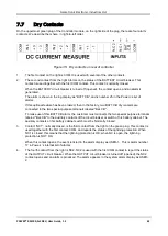
On the uppermost green plug of the Controller module, on the right side of the plug, there are four alarm
contacts. We describe them here, in right-to-left order.
Figure 35: Dry contacts on rear of controller
1
.
The first contact on the right is COM. It is used with several of the other contacts.
2
.
The second contact from the right informs on the status of the BATTERY circuit breaker. This
contact is used together with the first COM contact. This contact is normally closed.
When the BATTERY circuit breaker is turned off (opened), the contact opens, and an alarm is
generated.
The alarm is shown in the log display as “BATT CB”, and is number 25 in the Power+’s list of
alarms.
If this optional feature has been ordered, then in the factory, two BATT CB dry contacts are
connected to the two special-purpose terminals labeled "Bat. CB".
To make use of this BATT CB alarm, the customer must connects the two special purpose terminals
labeled "Bat. CB" to the auxiliary contacts of the circuit breaker or switch of his battery cabinet. The
auxiliary contacts on his battery cabinet switch must be Normally Closed.
3
.
Contact “NC1”, normally closed, is the third contact from the right on the green plug. This contact is
used together with the first contact, COM, and reports the status of the lightning protection. When
NC1 is closed, this means that the lightning protection is OK; when NC is open, the lightning
protection is NOT OK.
When this contact opens, the event is listed in the alarm display as USER-1. This is alarm number
17 in Power+’s internal list of alarms.
4
.
The fourth contact from the right is NC2. NC2 is used with the first COM contact to report the status
of the OUTPUT circuit breaker. When the OUTPUT circuit breaker is turned off (opened), the NC2
contact opens and an alarm is produced. The alarm appears in the system alarm display as USER-
2.
Содержание PowerPlus RM 100
Страница 27: ...Gamatronic Electronic Industries Ltd POWER RM100 3X208 V User Guide 1 3 13 Figure 7 Battery cabinet wiring...
Страница 44: ...Gamatronic Electronic Industries Ltd POWER RM100 3X208 V User Guide 1 3 30...
Страница 81: ...Gamatronic Electronic Industries Ltd POWER RM100 3X208 V User Guide 1 3 67 Figure 82 Service sub menu...
Страница 174: ...Gamatronic Electronic Industries Ltd POWER RM100 3X208 V User Guide 1 3 160 Table 21 List of SMS commands...


