background image

Gamatronic Electronic Industries Ltd. 


POWER+ RM100,


3

X

208


V, User Guide, 1.3 


147 

11.3.7.1


NETWORK CONFIGURATION 

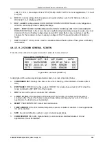
The “Network configuration” option on the Configuration menu is equivalent to navigating to 

Setup >


Service > SC2012 > Network

 on the Power+ physical control panel. Here you define the parameters 

needed to communicate with the Power+ over an intranet or over the Internet. Consult your local network 
administrator for the proper IP address, subnet mask, and Gateway address. 


Figure 300:  Configuring network communication parameters 


11.3.7.2


“DATE AND TIME” – SETTING THE CALENDAR AND CLOCK 

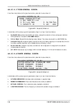
The “Date and time” option on the Configuration submenu is used to set the date and time of the Power+ 
internal calendar and clock. The date and time settings are important, for they are used to timestamp 
entries in the Power+ log. 

The date and time are kept current by the Power+, including when the system is in the “off” state. 

Click the Back button to return to the Configuration menu. 


Figure 301:  Setting the Power+ internal date and time 

Содержание PowerPlus RM 100

Страница 1: ...8222 Fax 972 2 582 8875 Email info gamatronic co il Website www gamatronic com 2MUM PP 28 POWER M MO OD DU UL LA AR R U UP PS S S SY YS ST TE EM M R RM M1 10 00 0 M MO OD DE EL L 3 3X X2 20 08 8 V VA...

Страница 2: ...onsible for any damage or malfunction due to incorrect wiring of the batteries Gamatronic is not liable for and the Purchaser waives any right of action it has or may have against Gamatronic for any c...

Страница 3: ...tenance bypass mode 16 6 USER INTERFACE 17 6 1 Control Panel 17 6 2 UPS Module Panel 17 6 3 Static Switch Panel 18 6 4 POWER control screen 19 6 4 1 Load level bar graph 19 6 5 Navigation and Operatio...

Страница 4: ...nu functions 64 10 POWER MENU FUNCTIONS IN DETAIL 69 10 1 Main Menu 69 10 2 System Option 70 10 3 UPS module Option 74 10 4 Self test Option 76 10 5 History logs Option 77 10 6 Battery Option 81 10 7...

Страница 5: ...actor Correction 124 10 12 6 Setting the SC2012 124 10 13 Setup Silicon Option 128 10 14 Static Switch option 130 10 15 System Controller Setup Verification 131 10 15 1 Setup Verification Menu 131 10...

Страница 6: ...forklift 1 Figure 3 Main subassemblies of the RM100 6 Figure 4 Battery cabinet 11 Figure 5 One battery box 12 Figure 6 One battery drawer 12 Figure 7 Battery cabinet wiring 13 Figure 8 Control panel...

Страница 7: ...display system under load 2 phase output 47 Figure 44 Connection diagram for completion by the customer 50 Figure 45 Main Menu 51 Figure 46 Password access 51 Figure 47 Setup menu 51 Figure 48 Servic...

Страница 8: ...PS Module 74 Figure 100 LCD Panel select a UPS 74 Figure 101 Module phase voltages currents 75 Figure 102 Battery voltages technician parameters 75 Figure 103 Main Menu option 3 Self Test 76 Figure 10...

Страница 9: ...Config setup menu 94 Figure 153 Select a phase to adjust 94 Figure 154 Select a module to adjust 94 Figure 155 Select a value to adjust 94 Figure 156 Module Config setup menu 95 Figure 157 Select the...

Страница 10: ...vated Auto test 108 Figure 202 Battery setup menu 108 Figure 203 Enable Disable shutdown by long AC failure 109 Figure 204 Main Menu option 7 Setup Charge Time Site Password 110 Figure 205 Level 1 pas...

Страница 11: ...125 Figure 256 Network menu 125 Figure 257 Setting an IP address 125 Figure 258 Network menu 126 Figure 259 Setting the gateway 126 Figure 260 Network menu 126 Figure 261 Setting the mask 126 Figure...

Страница 12: ...306 Defining email notification targets 152 Figure 307 Defining SMS recipients 153 Figure 308 Timing variables when using a generator and an ATS 154 Figure 309 Example of an ATS control panel 155 Figu...

Страница 13: ...for auto shutdown 150 Table 19 Fields in the email notifications screen 152 Table 20 Fields in the SMS notification target definition screen 153 Table 21 List of SMS commands 160 Table 22 Normal opera...

Страница 14: ...PACITE DE SORTIE EST AUGMENTEE AU DELA DE LA CONFIGURATION D ORIGINE LA PLAQUE INDICATIVE DU PRODUIT DOIT ETRE MISE A JOUR AVEC LES NOUVELLES CAPACITES Cette condition s applique si de nouvelles modul...

Страница 15: ...on the right side of the cabinet These flanges can be used to secure the RM100 to the ground if desired To move the RM100 cabinet with a forklift these flanges must be temporarily removed The same app...

Страница 16: ...ls the presence of a possibly serious life threatening condition Ensure all power is disconnected before performing installation or maintenance Leave at least 20 cm of clearance space between the vent...

Страница 17: ...five minutes CAUTION WARNING RISK OF LETHAL ELECTRIC SHOCK The battery drawer contains a series of 12 Volt batteries that provide high voltage and energy in the UPS body even when the UPS is not conn...

Страница 18: ...lisation d un conducteur neuter peut endommager en le syst me de fa on permanente CAUTION GROUND CONNECTION ESSENTIAL BEFORE CONNECTING SUPPLY Connect the UPS to ground before connecting it to the ac...

Страница 19: ...ry little attention or intervention during normal operation however you should read and understand the procedures described in this manual to ensure trouble free operation POWER is a parallel redundan...

Страница 20: ...ndustries Ltd POWER RM100 3X208 V User Guide 1 3 6 ITEM DESCRIPTION 1 19 inch cabinet 2 System controller module 3 From 1 to 10 UPS power modules 10 kVA each 4 Static switch assembly Figure 3 Main sub...

Страница 21: ...on capacity requirements Each module includes a 3 phase charger with PFC1 and a 3 phase PWM inverter connected to batteries by a classic dc link Each module is plug in and weighs a mere 22 lb 10 Kg ap...

Страница 22: ...RISK OF ELECTRIC SHOCK Do not touch uninsulated battery terminals CAUTION Do not dispose of battery or batteries in a fire The battery may explode For proper disposal contact your local recycling haza...

Страница 23: ...ge de gens du pays perte dangereuse ATTENTION N ouvrez pas ou ne mutilez pas la batterie ou les batteries L lectrolyte lib r est nocif la peau et aux yeux et est toxique ATTENTION Les batteries sont l...

Страница 24: ...re not suitable for a cabinet housing the batteries neither for the front cabinet door nor for the rear door If the UPS is delivered without batteries Gamatronic is not responsible for any damage or m...

Страница 25: ...connecting the external battery cabinet to the UPS connect the terminals according to the numbers That is connect battery cabinet terminal 1 above to battery terminal 1 on the UPS 2 to 2 3 to 3 and 4...

Страница 26: ...RM100 3X208 V User Guide 1 3 12 The battery cabinet cat no 29B020128 PPE contains two battery boxes Each battery box contains eight drawers of batteries Each drawer contains eight batteries Figure 5 O...

Страница 27: ...Gamatronic Electronic Industries Ltd POWER RM100 3X208 V User Guide 1 3 13 Figure 7 Battery cabinet wiring...

Страница 28: ...ntral column 9 Disconnect the green and yellow ground wire from each battery drawer 10 To check the batteries to see which of them need to be replaced you must remove each battery drawer one by one an...

Страница 29: ...of each mode of operation are described in the sections below 5 1 Normal operation The UPS is almost always in normal operation mode The load receives its power from the inverters that supply stabiliz...

Страница 30: ...utput terminals continue to supply power to the load but the interior of the UPS is disconnected from the main power flow This enables a maintenance technician to work safely on the UPS without any in...

Страница 31: ...CD display a keypad buttons and indicators for monitoring and controlling the UPS configuration and functions The control panel is aimed both at the end user as well as the service engineer All of the...

Страница 32: ...1 3 18 6 3 Static Switch Panel The static switch panel located on the front of static switch module provides the user with the status of the static switch module All the functions and indications are...

Страница 33: ...raph The load level bar graph on the default screen display illustrates the approximate load on each output phase of the UPS as a percent of the maximum available output for each phase The load on eac...

Страница 34: ...Operation Keypad The navigation and operation keypad works in conjunction with the control screen It allows you to navigate through the available menus using the direction arrow buttons and the Enter...

Страница 35: ...route Figure 13 Status indicators Table 1 Status indicators Ac Line Green Shows that the ac input is present and within range Alarm Red Flashes to indicate general alarm condition Battery Green Shows...

Страница 36: ...e engineer to manually change the operation mode Table 2 Operation buttons UPS ON OFF switch Alarm silence Inverter Bypass manual switch over 6 8 Network Access Indicator The network access indicator...

Страница 37: ...UPS OK ON L3 _______ 022A 120V STSW OK INV Figure 15 POWER control screen in normal operation Figure 16 Normal operation indication 6 9 2 Battery Operation During battery operation the battery supplie...

Страница 38: ...n Bypass mode Figure 20 Red alarm flashing 6 9 4 Bypass Operation Manual If the Power is manually switched to bypass operation by pressing the Inv Byp button the load is transferred to the mains ac in...

Страница 39: ...kVA system Choose the size of the protective circuit breakers according to the actual current as determined by the system capacity in kVA See Table 6 page 37 Battery cables 300 kcmils maximum 600 V 75...

Страница 40: ...external battery cabinet Note When connecting the external battery cabinet to the UPS connect the terminals according to the numbers That is connect battery cabinet terminal 1 to battery terminal 1 o...

Страница 41: ...ndustries Ltd POWER RM100 3X208 V User Guide 1 3 27 Figure 22 Cable entry from the top or bottom of UPS cabinet Figure 23 3 3 configuration below illustrates the cabling of the POWER system to the mai...

Страница 42: ...1 3 28 Figure 23 Connection diagram for 3 3 configuration Note If you intend to install the PowerPlus in a 2 2 configuration it is important that you first consult with Gamatronic s engineering depart...

Страница 43: ...the three phases This can result in serious damage to the UPS 7 2 1 A 4 pole switch might disconnect the neutral line WARNING If you have a mains to generator four pole switching system you are in dan...

Страница 44: ...Gamatronic Electronic Industries Ltd POWER RM100 3X208 V User Guide 1 3 30...

Страница 45: ...onic Electronic Industries Ltd POWER RM100 3X208 V User Guide 1 3 31 Figure 24 Wrong way to connect UPS with four pole switch WARNING A 4 pole switch may disconnect the neutral line if improperly conn...

Страница 46: ...Gamatronic Electronic Industries Ltd POWER RM100 3X208 V User Guide 1 3 32 Figure 25 Acceptable connection for grounded generator and 4 pole switch...

Страница 47: ...Gamatronic Electronic Industries Ltd POWER RM100 3X208 V User Guide 1 3 33 Figure 26 Preferred generator neutralized and connection 3 pole...

Страница 48: ...und Between a ground stud on UPS cabinet and the electrical board ground line or the ground connection on the load device Between a ground stud on the battery cabinet and the ground bus bar at the bot...

Страница 49: ...d Table 5 Figure 28 Crimp type cable shoes recommended for all ground cables Figure 29 Ground studs on UPS cabinet roof view from below Table 4 Key to Figure 29 ITEM GROUND NAME INSTRUCTIONS 1 INPUT G...

Страница 50: ...gure 30 and connect the other end of the cable to the ground bus bar at the bottom rear of the UPS Use a cable of 3 0 AWG and a tightening torque of 250 pound inches 28 2 N m on both ends of the cable...

Страница 51: ...ional au NSI NFPA 70 7 4 1 Ac wiring Ensure that the lines into and out of the UPS have protective circuit breakers installed in accordance with the ratings listed in Table 6 for your Power model The...

Страница 52: ...Ac input bypass Load 80 kVA Ac input 300 A Ac input bypass Load 90 kVA Ac input 350 A Ac input bypass Load 100 kVA Ac input 350 A Ac input bypass Load The recommended wire size is based on a 100 kVA s...

Страница 53: ...et estimation que l original AC INPUT FUSES Verify that the appropriate ac fuses are present In the ac distribution module the input for each UPS module is protected by a 32A fuse for each phase so th...

Страница 54: ...are present All dc fuses are located on the opposite side the front side of the dc distribution panel There are two fuses for each power module and for the controller one for the positive line and on...

Страница 55: ...ns on the rear of the controller module 7 6 1 Load on bypass alarm This output dry contact is Normally Open and closes when the UPS transfers the load to bypass The dry contact reopens again when the...

Страница 56: ...than 1 A 24 Vdc is recommended Verify continuity of the switch at its connection points before installing In the event that the POWER UPS is used in a computer room installation of the EPO switch is m...

Страница 57: ...to the two special purpose terminals labeled Bat CB To make use of this BATT CB alarm the customer must connects the two special purpose terminals labeled Bat CB to the auxiliary contacts of the circ...

Страница 58: ...ctions and fuses and 39 in 100 cm clearance at front for user access and service 6 Circuit breakers on the electrical board supplying the system Must be in accordance with Gamatronic system specificat...

Страница 59: ...ry Cabinets C B s Terminals and the UPS terminals Auxiliary contacts of Battery C B s are connected to UPS Controller inputs Bat CB and Com as marked 4 If an external battery cabinet is being used bef...

Страница 60: ...trol panel will show the following sequence The details of the display may vary from what is shown in the illustrations below depending on your system s particulars At start up the following screen se...

Страница 61: ...000A 120V BATTERY 432V L2 __________ 000A 120V UPS OK ON STSW OK INV Figure 41 Default screen with no load for 2 phase output 5 Switch all battery switches ON on all battery cabinets 6 You can now tur...

Страница 62: ...RED TO YOU WITH THE OUTPUT VOLTAGE AND FREQUENCY SET TO MATCH YOUR REQUIREMENTS CHECK NOW TO VERIFY THAT THESE SETTINGS ARE CORRECT TO SET MODULE S FREQUENCY SEE SECTION 10 9 2 ON PAGE 92 TO SET MODUL...

Страница 63: ...voltage of the system Total dc voltage between and terminals should be between 384 V and 432 V 4 Voltage between neutral and ground during operation under load On the input terminals of the system 0 2...

Страница 64: ...Gamatronic Electronic Industries Ltd POWER RM100 3X208 V User Guide 1 3 50 7 12 Connection diagram Figure 44 Connection diagram for completion by the customer...

Страница 65: ...45 Main Menu 2 From the Main Menu select option 7 Setup Main Menu SETUP POWER System Setup Type in Level 1 PASSWORD THEN ENTER Your privilege will expire after 15 min PASSWORD ________ Figure 46 Pass...

Страница 66: ...tch Setup 8 REM COMMAND Figure 49 Configure menu 7 Use the arrow keys to specify the total number of modules installed in the Power and then press Ent Main Menu SETUP password Ent Service Configure OF...

Страница 67: ...er 1 From the Main Menu select option 5 Battery Main Menu BATTERY Battery capacity 0020Ah Charge mode Floating Eq running time Charge current 053 0A Figure 52 Battery status The battery status panel d...

Страница 68: ...the Power system in the System Controller and then press Ent Main Menu SETUP password Site Site number 013271 Figure 56 Site number Note The serial number of Power is on a bar code label at the bottom...

Страница 69: ...58 IP Address 4 Use the arrows keys to set the gateway and press Ent Main Menu SETUP password Ent Service SC2012 Network Set GATEWAY Set GATEWAY 157 211 000 251 Figure 59 Gateway 5 Select Store Main M...

Страница 70: ...o the UPS 2 Turn On the switch to the dc input from the batteries only 3 Wait approximately 2 minutes for Power to initialize see Section 7 10 First time Startup 4 Measure the phase to neutral voltage...

Страница 71: ...omputer to the Ethernet RJ45 port on the rear panel of the UPS s system controller Configure the network connections of the external computer so that the computer is in the same domain as the UPS that...

Страница 72: ...b interface of Wing to a specified phone number 1 Click the Send SMS button on the left sidebar of the Main Screen of the built in web server 1 Figure 62 Login screen of built in web server 2 When the...

Страница 73: ...__ 000A 120V UPS OK OFF L3 __________ 000A 120V STSW OK BYP Figure 64 Main screen after a power shutdown Figure 65 Main screen after a power shutdown indication 1 Press twice on the On Off button on t...

Страница 74: ...n 2 Connect the load and observe the results on the display LOAD LEVEL 11 20 25 L1 _____ 030A 120V BATTERY 432V L2 ______ 024A 120V UPS OK ON L3 _______ 022A 120V STSW OK INV Load level bar graph Outp...

Страница 75: ...2 minutes for the POWER to shut down The control screen will indicate UPS OK OFF LOAD LEVEL 22 21 18 L1 __________ 000A 120V BATTERY 432V L2 __________ 000A 120V UPS OK OFF L3 __________ 000A 120V ST...

Страница 76: ...1 Switch the load OFF 2 Press and hold the On Off button for 10 seconds 3 The control screen will indicate UPS OK OFF LOAD LEVEL 23 14 40 L1 __________ 000A 120V BATTERY 432V L2 __________ 000A 120V U...

Страница 77: ...e control panel serves as the user s primary interface with the system Messages warnings and error conditions are relayed to the user through the display LEDs and audible alarms Figure 73 Control pane...

Страница 78: ...reference summary of Power menu functions The following flowcharts detail the structure of the PowerPlus menus The symbol directs you to a following chart For example means go to the diagram labeled M...

Страница 79: ...3X208 V User Guide 1 3 65 Figure 75 System menu Figure 76 Battery menu Figure 77 Setup menu Inverter voltage Bypass voltage Output current Static switch status bytes Main Menu STATIC SW 8 Displays M 8...

Страница 80: ...high low alarm thresholds Ac alarm hysteresis 2 Batt end batt low batt hi voltages 7 Over temp under temp 9 Integration factor Options 1 on the Setup menu Setup Menu ALARM SET Set M 7 1 Figure 79 Ala...

Страница 81: ...Gamatronic Electronic Industries Ltd POWER RM100 3X208 V User Guide 1 3 67 Figure 82 Service sub menu...

Страница 82: ...Gamatronic Electronic Industries Ltd POWER RM100 3X208 V User Guide 1 3 68 Figure 83 Configure sub sub menu Figure 84 Silicon sub menu...

Страница 83: ...ime press the Escape button Esc and then Ent 1 SYSTEM 4 HISTORY 7 SETUP 2 UPS MODULE 5 BATTERY 8 STATIC SW 3 SELFTEST 6 ALARM 9 _____ NAVIGATE UP DOWN 1 SELECT ENTER Figure 85 Main menu Table 10 Main...

Страница 84: ...0 2 System Option Figure 86 Main menu option 1 System 1 The SYSTEM option option 1 shows the dc voltages and current positive negative and summary Main Menu SYSTEM BATT CURR TOTAL 053 0A BATT POS 216V...

Страница 85: ...2 0A 120V 021 0A OUT 120V 021 0A 120V 021 0A 120V 021 0A TOTAL UPS IN OUT MEASUREMENTS Figure 90 Overall phase voltages currents 5 View the total time current session time and boots so far Main Menu S...

Страница 86: ...that the configuration jumper is installed thus allowing for modifications Hard Silicon indicates that the factory defaults hard reset jumper is installed This is required only at the factory or whene...

Страница 87: ...for Technicians Main Menu SYSTEM PD DIALOG UPS 01 T c0 42 00 00 d8 00 00 00 00 00 00 00 00 00 00 00 00 00 00 aa Figure 97 Communication with inverter transmit 12 View communication with the converter...

Страница 88: ...the voltage and current measurements for each module see Figure 101 on page 75 2 Scroll and keys to view additional information for the specific module chosen Figure 99 Main Menu option 2 UPS Module...

Страница 89: ...ASE L1 L2 L3 IN 000V 000 0A 000V 000 0A 000V 000 0A OUT 000V 000 0A 000V 000 0A 000V 000 0A UPS 01 04 Figure 101 Module phase voltages currents 3 View the battery voltage for the selected UPS module t...

Страница 90: ...f test alarm The self test alarm can only be cleared by a subsequent successful self test or it can be cleared manually by a maintenance technician Powering the POWER down and up for example does not...

Страница 91: ...ved in the LOG are displayed as shown in Figure 106 Figure 105 Main Menu option 4 History 1 Navigate the LOG by scrolling using the and keys Main Menu HISTORY TIME DATE VALUE MESSAGE 14 36 16 28 06 07...

Страница 92: ...uide 1 3 78 2 View more details by pressing the key Main Menu HISTORY TIME DATE 1 2 3 4 5 6 7 8 14 36 16 28 02 10 254 14 37 01 28 02 10 255 12 27 26 27 02 10 000 Figure 107 History log scroll Table 11...

Страница 93: ...tery backup Battery is discharged to shutdown limit 12 BATLOW Low battery voltage 13 STSWRN Static Switch Warning or alarm 14 E P O Emergency Power Off is active 15 EQ HST Battery is currently chargin...

Страница 94: ...witch transfer code LOADBP The STSW transfer code given as a decimal is the sum of the eight components listed in this table Each component has its own weight if detected and a weight of zero if not d...

Страница 95: ...plays information about battery capacity battery voltage and current and battery test Figure 108 Main Menu option 5 Battery 1 View the battery capacity charge mode equalizing running time and charge c...

Страница 96: ...izing 3 View the maximum estimated time left battery test in progress time battery voltage battery charging current last test result and days left Main Menu BATTERY Max estim time left 00 00 00 Batter...

Страница 97: ...Figure 113 and Figure 114 show the individual batteries on the left and the overall total on the right In the examples shown above only one battery is installed 7 View battery charging current limit M...

Страница 98: ...the alarm is active Main Menu ALARM 01 03 UPSMAJ UPSMIN MSTR 1 04 06 DCRPCY LOADBP VIBRA 07 09 OVTEMP OUTFLT BAT HI 10 12 BATEND BATLOW Figure 117 Alarms 01 12 2 View alarms 13 24 Main Menu ALARM 13 1...

Страница 99: ...arge alarm setup voltage setting Floating charge alarm setup voltage setting Floating charge alarm setup voltage setting 1 Over temperature 2 Under temperature Set over temperature alarm value Set und...

Страница 100: ...T 1 AC VOLT 5 9 INTEGRAT 2 FLOAT VOLT 6 3 7 TEMPERATURE 4 8 Figure 123 Alarm setup menu 2 Select Set AC High Low Alarm Levels Main Menu SETUP Ent password Ent ALARM SET AC VOLT 1 SET AC HIGH LOW ALARM...

Страница 101: ...en Esc Main Menu SETUP Ent password Ent ALARM SET AC VOLT Set AC Alarms Hysteresis SET AC VOLT ALARMS HYSTERESIS VALUE 1 20 VOLT 05 Figure 127 Set ac voltage hysteresis 10 8 2 Setting Battery Floating...

Страница 102: ...1 Battery floating charge alarm setup menu 5 Use the arrow keys to set BATLOW and press Ent Main Menu SETUP password ALARM SET FLOAT VOLT BATLOW FLOATING CHARGE ALARM SETUP VOLTAGE SETTING 170 0V Figu...

Страница 103: ...M SET Temperature 1 OVER TEMPERATURE 2 UNDER TEMPERATURE PLEASE SELECT Figure 136 Over Under temperature menu 3 Use the arrow keys to set the battery maximum temperature alarm value and press Ent Main...

Страница 104: ...ermine the UPS status before deciding on an error status Setting the alarm integration factor too low will cause spurious alarms to be generated conversely setting the alarm integration factor too hig...

Страница 105: ...e s voltage Update Vo Fr ph settings Select A Phase To Adjust Select A Module To Adjust Select A Value To Adjust Set frequency limits 1 Calibrate Positive Voltage 2 Calibrate Negative Voltage Set Posi...

Страница 106: ...Calibration 4 Update Vo Fr ph 8 AC Calibration Figure 145 Module Config setup menu 10 9 2 Setting Module s Frequency 1 Select Module s frequency Main Menu SETUP password Module conf 1 Num of phase 5 O...

Страница 107: ...tage Module s voltage 4 118V 1 110V 5 120V 2 113V 6 125V 3 115V selected 5 130V Figure 149 Setting the Module s voltage 10 9 4 Update Voltage Frequency Phase 1 Select Update Vo Fr ph Main Menu SETUP p...

Страница 108: ...nt Main Menu SETUP password Module conf Output Adjust Select a phase to adjust Select 1 L1 Select 2 L2 Select 3 L3 Figure 153 Select a phase to adjust 3 Using the keys select a module to adjust and th...

Страница 109: ...s 1 No Change 4 3Hz 2 1Hz slctd 5 4Hz 3 2Hz 6 0 5Hz Figure 157 Select the frequency limits 10 9 7 Calibrating DC Voltage 1 Select DC Calibration Main Menu SETUP password Module conf 1 Num of phase 5 O...

Страница 110: ...cy Limits 3 Module s voltage 7 DC Calibration 4 Update Vo Fr ph 8 AC Calibration Figure 161 Module Config setup menu 2 Select either Calibrate INPUT Voltage or Calibrate OUTPUT Voltage and then press...

Страница 111: ...ature compensation 1 Set ABSOLUTE MINimum Output Voltage 2 Set ABSOLUTE MAXimum Output Voltage Set ABSOLUTE MINimum Voltage while Cmpensat Set ABSOLUTE MAXimum Voltage while Cmpensat 2 Set Auto Batter...

Страница 112: ...arm set 5 Time 9 Silicon 2 Module conf 6 Site 3 Battery 7 Password 1 4 Charge 8 Service Figure 166 Setup menu 10 10 1 Setting Battery Test Voltage 1 Select Test Voltage Main Menu SETUP password Batter...

Страница 113: ...d Battery 1 Test Voltage 5 Battery test 2 Test Alarm 6 Capacity 0020 AH 3 Current Limit 7 AuTo Test 4 Temp Compensat 8 Enable Dis Options Figure 169 Battery setup menu 2 Using the arrow keys set the b...

Страница 114: ...ry Current Limit 1 Current Limit Value Setup 2 Current Limit Press to ENABLE 1 Press 2 to Toggle Enable Disable Figure 172 Current Limit setup menu 3 Select the current limit for each battery and pres...

Страница 115: ...alue Setup and press Ent Main Menu SETUP password Battery Current Limit 1 Current Limit Value Setup 2 Current Limit Press to ENABLE 1 Press 2 to Toggle Enable Disable Figure 176 Current Limit setup me...

Страница 116: ...u 2 Select Temperature compensation Value Setup and press Ent Main Menu SETUP password Battery Temp Compensat 1 Temperature Compensation Value Setup 2 Disable Temp Compensation 2 0 mV 3 Set ABSOLUTE M...

Страница 117: ...at 1 Temperature Compensation Value Setup 2 Enable Temp Compensation OFF 3 Set ABSOLUTE Max Min Voltages 1 Press 2 to toggle enable disable 1 Temperature Compensation Value Setup 2 Disable Temp Compen...

Страница 118: ...mpensat Absolute minimum voltage while cmpensat Voltage setting 400 0V Figure 185 Set absolute minimum output voltage when compensating 4 Select Set absolute maximum output voltage Main Menu SETUP pas...

Страница 119: ...battery test 2 Set auto battery test period 3 Set auto battery test top time 1 Figure 189 Select Activate Battery Test 3 Press Ent to start stop test and then press Esc Main Menu SETUP password Batter...

Страница 120: ...Battery test Set Auto Battery Test Period Set batt test period 1 50 weeks Figure 193 Set battery test period 10 10 10 Setting the Automatic Battery Test Top Time 1 Select Battery test Main Menu SETUP...

Страница 121: ...e 5 Battery test 2 Test Alarm 6 Capacity 0020 AH 3 Current Limit 7 AuTo Test 4 Temp Compensat 8 Enable Dis Options Figure 197 Battery setup menu 2 Select Set Capacity of Battery 1 and then press Ent M...

Страница 122: ...menu 2 The test is performed Press Ent when done Main Menu SETUP password Battery Auto Test Max estim time left 00 00 00 Battery test in progress for 00 00 00 Batt volt 400 0V Batt current 010 Last t...

Страница 123: ...DISABLE SHUTDOWN by long AC FAIL On 2 ENABLE Current Sensors Off 3 ENABLE BATT Temperature sensor Off Select Press To toggle Enable Disable Figure 203 Enable Disable shutdown by long AC failure Note O...

Страница 124: ...and Password SUBMENU OPTIONS 2 Floating Parameters Setup FLOATING CHARGE SETUP 5 Time 6 Site 7 Password Set real time Set site number Change password Figure 204 Main Menu option 7 Setup Charge Time Si...

Страница 125: ...attery 7 Password 1 4 Charge 8 Service Figure 206 Setup menu 2 Select Floating parameters setup Main Menu SETUP password Charge 1 2 Floating parameters setup 3 Eq off 4 1 Figure 207 Charge setup menu...

Страница 126: ...password Time Set real time Year Month Day Hour Min Sec 2011 09 30 23 58 00 Figure 210 Set date and time 10 11 3 Setting the Site Number 1 Select Site Main Menu SETUP password Ent 1 Alarm set 5 Time...

Страница 127: ...1 Main Menu SETUP password Ent 1 Alarm set 5 Time 9 Silicon 2 Module conf 6 Site 3 Battery 7 Password 1 4 Charge 8 Service Figure 213 Setup menu 2 Use the arrow keys to change the password and press...

Страница 128: ...r Ent Service SUBMENU OPTIONS 8 Service Password 5 Configure 8 Powr Calib Press repeatedly to check each relay CURRENT SHARING RESET Select 1 Disabled or 2 Enabled Ent Set power factor correction Ent...

Страница 129: ...I Calibration To remove current offsets first disconnect batteries and load Ent or Esc Calibrate battery N current Enter actual current value for N current Select 1 Standalone or 2 Parallel Ent Remote...

Страница 130: ...e 1 4 DryOut Test 7 2 UPSs 5 Configure 8 Powr Calib 3 6 En Dis shar 9 SC2012 Select then Enter Figure 219 Service menu 2 Use the arrow keys to set UPSs and press Esc when finished Main Menu SETUP pass...

Страница 131: ...5 Configure 8 Powr Calib 3 6 En Dis shar 9 SC2012 Select then Enter Figure 223 Service menu 10 12 3 1 NUMBER OF REDUNDANT UPSS 1 Select OF UPSs redundancy Main Menu SETUP password Ent Service Configu...

Страница 132: ...t Main Menu SETUP password Ent Service Configure OF UPSs total Set number of UPSs total 04 02 redundant Figure 227 Set total number of UPSs 10 12 3 3 TOTAL NUMBER OF BATTERIES 1 Select OF BATT Main Me...

Страница 133: ...COMMAND Figure 230 Service Configure menu 2 Select Set mask Main Menu SETUP password Ent Service Configure Static Switch Setup 1 Set mask 2 Configure BYPASS Figure 231 Static Switch setup menu 3 Use a...

Страница 134: ...association 5 dry5 association 3 dry3 association 6 dry6 association 7 enable disable alarms Figure 235 Dry relay menu 3 Use arrow keys to set associations between dry contacts and alarms and then pre...

Страница 135: ...t removal Main Menu SETUP password Ent Service Configure Calibration 1 5 2 DC I Offset removal 6 3 DC I Calibration 7 4 Select Figure 239 DC I menu 3 Follow screen instructions Main Menu SETUP passwor...

Страница 136: ...ue of the actual current 02000 X0 1 A Figure 243 Entering actual current 10 12 3 7 SELECTING STANDALONE OR PARALLEL OPERATION 1 Select Parallel StandAlone Main Menu SETUP password Ent Service Configur...

Страница 137: ...password Ent Service Configure REM COMMAND REMOTE COMMANDS EN DIS SELECT 1 Disable selected SELECT 2 Enable Figure 247 Enabling disabling remote commands 10 12 4 Enabling Disabling Current Sharing 1 S...

Страница 138: ...Set power correction factor value Current Value 01 Value to modify 02 Use Up down Enter Or Esc Figure 251 Enabling disabling power factor correction 10 12 6 Setting the SC2012 1 Select SC2012 Main Men...

Страница 139: ...etwork Main Menu SETUP password Ent Service SC2012 1 Restart controller 3 Network 2 Factory settings 4 Reset MBX Your selection 1 5 Enter if you are sure else press Esc Figure 255 SC2012 menu 5 Select...

Страница 140: ...gateway and press Ent Main Menu SETUP password Ent Service SC2012 Network Set GATEWAY Set GATEWAY 157 211 000 251 Figure 259 Setting the gateway 9 Select MASK Main Menu SETUP password Ent Service SC20...

Страница 141: ...et IP ADDRESS 157 211 000 253 2 Set GATEWAY 157 211 000 251 3 Set MASK 255 255 255 000 4 Store 5 SNMP factor Select 1 Figure 263 Network menu 13 Use the arrows keys to set the SNMP NO COMM Factor pres...

Страница 142: ...lts 3 Save User Defaults 9 Silicon Service SUBMENU OPTIONS Figure 266 Main Menu option 7 Setup Static Switch 1 To enter Setup use the default password left arrow key eight times Main Menu SETUP POWER...

Страница 143: ...e 270 Silicon menu 5 Select Restore Factory Defaults Restore User Defaults or Save User Defaults Main Menu SETUP password Ent Silicon Defaults 1 Restore Factory Defaults 2 Restore User Defaults 3 Save...

Страница 144: ...EM UPS MODULE SELFTEST HISTORY BATTERY ALARM SETUP STATIC SW Figure 274 Static switch option 1 View the static switch voltage and frequency Main Menu STATIC SW SSW VOLTAGE FREQ INVERTER L1 120V L2 120...

Страница 145: ...irmware and communication revisions View the IP Gateway Mask and Faults Set the menu language to English Spanish or Portuguese Ent Ent First screen 10 viewable system parameters Second screen 7 more v...

Страница 146: ...Ss 10 15 3 On Off Status of UPSs In the screen shown in Figure 280 UPSs 1 3 are on UPS 4 is off and UPSs 5 9 are non existent 3 second Esc UPSs On Off Stat 123456789 UPS Figure 280 On Off status of UP...

Страница 147: ...15 6 Dry Input and Output Relay Contact Status The input and output contacts for the Power are displayed in Figure 283 input relay contacts 1 and 3 are closed and all other contacts are open The outp...

Страница 148: ...TEMP ALARM 45C MODULES 07 02 C LIM off T C 2 0mV DCV 216 ALM 475 360 340 BATT TEST 04 05 360 352 CAP 0010 AH Figure 287 General Screen 1 a ACV nominal value of the input output ac voltage 220 for 2x32...

Страница 149: ...wn in the previous section press to view screen 2 3 second Esc GENERAL CURRSHARE RST DIS OF PHASE AUTO REV SC25230909 LVD BY AC FAIL DIS MAINT 2010 05 12 TEMP SENSOR DIS SITE 000001 CURR SENSOR DIS Fi...

Страница 150: ...more less than 100 Ah to achieve optimal resolution of the displayed value of battery current d No Yes Rmt Pan Outputs of system controller are not configured or configured for an optional remote pane...

Страница 151: ...fault password is 8 left arrows Service SC2012 Network b From the Network menu choose IP Address and enter the assigned IP address c From the Network menu choose Gateway and enter the assigned Gateway...

Страница 152: ...lable A signal strength indicator is displayed along with the service provider name Cellular communication requires the Wing module Site number The site number is identified Date and time The current...

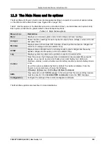
Страница 153: ...and currents dc voltage and active alarms if any STSW Displays status of Static Switch including inverter output voltages and frequency bypass voltages and frequency and active alarms if any Log Displ...

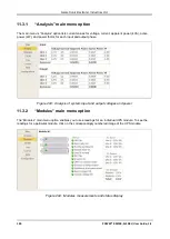
Страница 154: ...tive power kW and power factor for each input and output phase Figure 293 Analysis of system input and output voltages and power 11 3 2 Modules main menu option The Modules main menu option enables yo...

Страница 155: ...Static Switch option on the main menu displays the real time voltage and frequency measurements for the inverter output voltage and the bypass voltage This screen also displays a wealth of additional...

Страница 156: ...entries Table 15 Data items on the event log screen MENU OPTION DESCRIPTION ID This is simply a line number In Out In indicates the start of an alarm condition Out indicates the end of an alarm condi...

Страница 157: ...ion lost 0 Communication lost 32 Emergency Power Off Activated 14 End of Backup 11 Equalizing mode 15 HIGH Battery voltage 9 Input Brownout 20 Last battery test 16 Last self test fail 24 Load current...

Страница 158: ...er Start battery test Initiates a battery test Note it is recommended that a battery test not be initiated when the when the UPS is operating near 100 capacity and at the same time the battery is know...

Страница 159: ...age 150 will be shut down Simulate UPS battery status is low clicking on this link simulates the conditions in effect after an extended ac power failure a signal is sent via SNMP to any connected comp...

Страница 160: ...mpt for a user ID and password The factory default user ID is admin and the factory default password is also admin These default values for the user ID and password can be changed as is explained belo...

Страница 161: ...rator for the proper IP address subnet mask and Gateway address Figure 300 Configuring network communication parameters 11 3 7 2 DATE AND TIME SETTING THE CALENDAR AND CLOCK The Date and time option o...

Страница 162: ...ntry into the options on the Web interface s Configuration submenu The factory default user ID and password are admin and admin The new user ID and password must each have a minimum of four characters...

Страница 163: ...modify G4 settings You also have the capability of limiting the IP addresses from which the G4 will accept SNMP packets If the IP address has 4 segments of zero 0 0 0 0 this means that all users in t...

Страница 164: ...he Internet by clicking on the Shutdown Agent link in the bottom right of the screen as shown in Figure 305 Note The built in Web interface supports a maximum of 15 shutdown targets Customers requirin...

Страница 165: ...ower returns the Shutdown Agent saves and closes any open datasets on the computer and then shuts the computer down If during the countdown the Power battery falls below a preset voltage the low batte...

Страница 166: ...ations screen FIELD DESCRIPTION SMTP server address DNS name or IP address of the outgoing email server The Power must be defined to the email server as NOT requiring a login SMTP port Predefined SMTP...

Страница 167: ...define telephone numbers that are to receive notification via SMS in the event of specific alarm conditions on the Power Figure 307 Defining SMS recipients Table 20 Fields in the SMS notification tar...

Страница 168: ...an Automatic Transfer Switch ATS Because these two sources are not usually synchronized switching between them requires an interval of at least 10 seconds Figure 308 illustrates the timing factors inv...

Страница 169: ...is the reserve source The timing variables T1 through T5 are described in Figure 308 The knob at the bottom of the control panel controls the actions of the ATS The ATS can be set to use the normal so...

Страница 170: ...the SNMP agent can perform an automatic orderly shutdown of Windows computer systems before the UPS batteries run out A small shutdown client must be installed on each target computer The SNMP agent...

Страница 171: ...Wing unit that has been ordered specifically for use with a Power system If your Wing was ordered for use with another type of system it does not contain the appropriate software for use with a Power...

Страница 172: ...IP address of the Power into the URL bar and press Enter The home page of the Power web interface is displayed If you do not know the Power s IP address you can see it by pressing and holding the Esc...

Страница 173: ...m any cellular telephone To see a log of the incoming and outgoing SMS messages choose SMS in the menu column at the left side of the web page To see a list of the available SMS commands on the SMS sc...

Страница 174: ...Gamatronic Electronic Industries Ltd POWER RM100 3X208 V User Guide 1 3 160 Table 21 List of SMS commands...

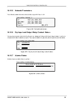
Страница 175: ...me delay Include internal GSM modem quad band for an additional remote control and management link without LAN dependency Bi directional control via simple SMS commands Automatic response to sensed ev...

Страница 176: ...user defined time delay Auto wake up of servers on restoration of ac power after user defined time delay Include internal GSM modem quad band for additional backup control management without LAN depe...

Страница 177: ...bypass indicator is lit on the Static Switch If it is not lit the UPS cannot go into bypass mode 2 On the Controller front panel press the INV BYP button twice to put the UPS in bypass mode 3 Verify t...

Страница 178: ...t breaker 4 Switch ON the UPS refer to section 8 1 Start up after Shutdown on page 59 5 Press the INV BYP button twice to put the UPS into bypass mode 6 Verify that the bypass indicator is lit on the...

Страница 179: ...ee period Gamatronic bears no liability for damage caused to the UPS due to improper maintenance by third parties in particular after the expiration of the warrantee or service agreement It is the res...

Страница 180: ...c resp to 100 load step 2 Overload 110 for 10 min 125 for 60 sec 1000 for 1 cycle Waveform Sinusoidal THD Less than 2 for linear load Load CF 4 1 Ac Ac efficiency nominal Up to 94 at full load Dc Ac e...

Страница 181: ...0 mm 42U W 600 mm D 1000 mm UPS CAPACITY KVA 10 20 30 40 50 60 70 80 90 90 N 1 Weight lbs 424 446 469 491 514 536 559 581 604 626 Weight kg 192 2 202 4 212 6 222 8 233 0 243 2 253 4 263 6 273 7 284 0...

Страница 182: ...contacts 6 outputs rated 50V 1A RS232 user port Yes isolated Optional communication TCP IP GPRS SMS wireless communications optional Communications with system modules Serial isolated Events log 255 e...

Страница 183: ...rters Dc to Dc Converters Frequency Converters Battery Chargers Power Management Solutions Headquarters and Factory 17 Hartom Street Har Hotzvim Industries Park POB 45029 Jerusalem 9777517 Israel Tel...

Отзывы: