background image


DairyScale


Installer


manual


3E0673


Page


24


DAIRYSCALE


ENGINEERING


OPTIONS


MENU


The


Engineering


menu


lets


you


change


various


options


on


the


Scale.


The


following


options


are


available


in


the


Engineering


menu:


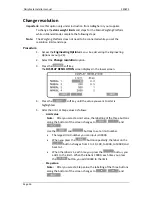
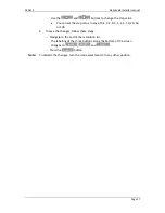
Change


auto


weighing


Change


span


Change


resolution


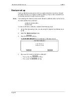
Restore


set


up


Accessing


the


DairyScale


Engineering


Options


menu


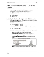
The


Engineering


Options


menu


is


a


hidden


menu


which


enables


you


to


change


settings


used


to


configure


the


Scale.


Procedure


1.


Turn


the


mode


select


switch


to


S

.


2.


Press


the


and


soft


keys


,


as


required,


to


select


USER


OPTIONS

.


3.


Press


the


SELECT


soft


key.


4.


Once


the


USER


OPTIONS


view


displays


on


the


lower


screen,


press


buttons


in


the


following


sequence.


Green


red


blue


blue




red


right


hand


soft


key.


The


ENGINEERING


OPTIONS


menu


displays


in


the


lower


screen.


5.


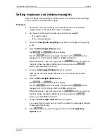
Select


the


Change


auto


weighing


option.


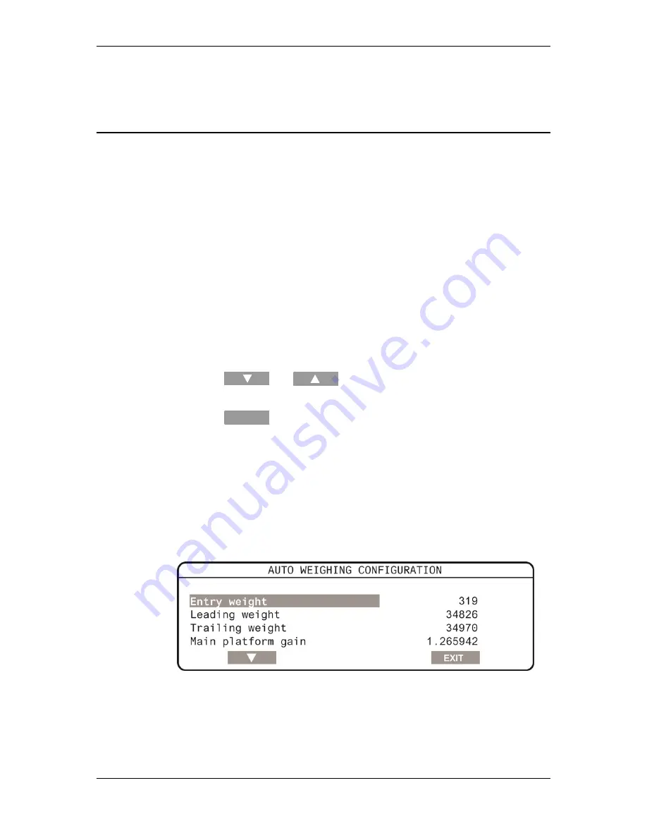
The


AUTO


WEIGHING


CONFIGURATION


menu


displays


in


the


lower


screen.


Note:


The


values


shown


above


may


vary


depending


on


your


installation.


Содержание DAIRY SCALE XDS5000

Страница 1: ...Installer Manual ENG DAIRY SCALE XDS5000...

Страница 2: ...has been made to ensure accuracy neither Gallagher Group Limited nor any employee of the company shall be liable on any ground whatsoever to any party in respect of decisions or actions they may make...

Страница 3: ...ing maximum and minimum weights 22 Testing the Scale 23 Testing the Panel Reader 23 DairyScale Engineering Options menu 24 Accessing the DairyScale Engineering Options menu 24 Change auto weighing 25...

Страница 4: ......

Страница 5: ...Installation section prior to planning each DairyScale installation The location of the Chicane Weighing Platform set and Panel Reader are inter related and for each installation you will need to dete...

Страница 6: ...ed from the Scale onto a computer The Scale can also produce a real time output of EID number and valid weight as each animal is weighed Installation considerations While planning the installation tak...

Страница 7: ...tall the Power Supply in a cool dry place close to a power point 2 Run the 12V cable from the Power Supply to the Scale Gallagher recommends that all cabling is mounted within conduit or similar to pr...

Страница 8: ...e concrete under the Weighing Platform set must be as level as possible The Weighing Platform must be level and both platforms must be even in height Chicane dimensions The following is a diagram of a...

Страница 9: ...3E0673 DairyScale Installer manual Page 5 Chicane and Weighing Platform dimensions...

Страница 10: ...ss Materials Dyna bolts Galvanised 12 mm x 25 mm if direct on to concrete or 12 mm x 100 mm if spacers are required Electric drill with masonry drill bit Step 1 Assembly of the Scale Lead on Frame Imp...

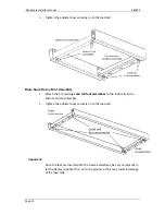
Страница 11: ...on a flat surface ensuring that the rails are parallel and fully tighten all of the bolts Step 2 Assembly of the Scale Main Frame Important When attaching each part with the M12 x 25mm galvanised bolt...

Страница 12: ...nd Crossmember and attach to the Main rail using 3 x M12 x 25 galvanised bolts 3 Attach the second Main Rail using 6 x M12x25 galvanised bolts 4 Place the frame assembly on a flat surface ensuring tha...

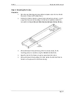
Страница 13: ...ot fully tighten 2 Repeat this a further 7 times so there are eight assemblies 3 Two of these assemblies form the Lead on foot assemblies Put these to one side 4 With the remaining 6 assemblies thread...

Страница 14: ...ttach the 4 remaining Load cell foot assemblies to the load cells in the Main Scale Crossmember 2 Tighten the adjuster boss securely on to the load cell Important Once the feet are inserted into the f...

Страница 15: ...ch a way that the cows are travelling on to the lead on platform before the main platform Ensure there is 10mm clearance between the two frames 3 When satisfied with the positioning of the Frame assem...

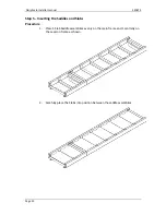
Страница 16: ...Page 12 Step 5 Inserting the Saddles and Slabs Procedure 1 Place 5 Slab Saddle assemblies evenly on the main frame and 1 centrally on the Lead on frame as shown 2 Carefully place the Slabs into posit...

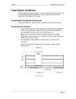
Страница 17: ...ions Mounting the Panel Reader 1 Mount the Panel Reader on the outside of the race with the leading edge of the Panel Reader approximately 1100 mm from the leading edge of the Main Weighing Platform a...

Страница 18: ...ead onto the Scale bracket 3 Connect the Scale power supply cable 4 Set up the Scale as per the User manual You need to set up the following Set the time and date in the Scale Set the User Options Ass...

Страница 19: ...he Junction box Two short tails from the Junction box will plug into the Scale head Mount the Scale head undercover in the Dairy shed with the loadcell cables routed into the shed Note The yellow Amph...

Страница 20: ...2 port on the Scale 2 Connect the Scale power supply cable to the Scale Note Warning messages are displayed on the Scale if the Weighing Platforms are plugged in incorrectly or are not plugged in The...

Страница 21: ...er to Change auto weighing p 25 Note The values shown above may vary depending on your installation 2 Write down the values for the following fields Entry weight Leading weight Trailing weight 3 Stand...

Страница 22: ...alue you wrote down If yes the trailing edge Load cells on the Main platform are functioning correctly If no the trailing edge Load cells on the Main platform are malfunctioning See below for details...

Страница 23: ...d to calibrate the Scale Span weight During the calibration process the Scale uses the above values to estimate the test weight The estimated weight is displayed in this field Correct the displayed we...

Страница 24: ...ptured the Scale can not be calibrated to the Weighing Platform See Fixing calibration problems p 21 for more details 6 Place the known weight on the trailing edge of the Main Weighing Platform 7 Pres...

Страница 25: ...hout pressing The Scale reverts to normal operation without saving the changes Note Once the calibration information is captured it is stored with the factory defaults It is not lost if the factory de...

Страница 26: ...ck to 1 When the label is 1 each time you press the 1 button you add 1 to the limit When the label is 10000 each time you press the 10000 button you add 10000 to the limit 5 Increase the Min weight al...

Страница 27: ...ht dirt or manure left on the platform 4 Place the calibrated weight in the middle of the Main platform The Scale displays the weight of the object 5 If the displayed weight correct If yes the Scale i...

Страница 28: ...ch enables you to change settings used to configure the Scale Procedure 1 Turn the mode select switch to S 2 Press the and soft keys as required to select USER OPTIONS 3 Press the SELECT soft key 4 On...

Страница 29: ...nd increases as weight is applied on the Load cells In normal operation with no weight on the platform the displayed value should be between 31700 and 32700 Trailing weight This is the raw Analogue to...

Страница 30: ...lower screen 4 Press the soft key until the value you want to alter is highlighted 5 Alter the Limit or Step values as follows Limit value Note After you select a Limit value the labelling of the thr...

Страница 31: ...ny of 0 1 0 2 0 5 1 2 5 10 20 50 or 100 6 To save the changes follow these steps Navigate to the end of the resolution list The labelling of the three buttons along the bottom of the screen changes to...

Страница 32: ...ults and is not lost when the factory defaults are restored Calibration information Scale Model To restore the factory defaults complete the following steps 1 Access the Engineering menu See Accessing...

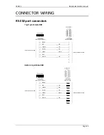
Страница 33: ...IEWED FROM CABLE SIDE OF SOCKET EHR 7 SOCKET 7 6 5 4 3 2 1 4 6 6 7 8 9 1 2 3 4 5 VIEWED FROM REAR OF SOCKET D SUB SOCKET RXD TXD RTS EARTH CTS Bottom 9 pin Male DB9 1 2 3 4 5 6 7 1 3 2 8 5 9 7 PRINTED...

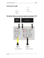
Страница 34: ...DairyScale Installer manual 3E0673 Page 30 Scale power supply Weighing Platform connectors before December 2013 Left side of indicator Right side of indicator...

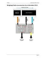
Страница 35: ...3E0673 DairyScale Installer manual Page 31 Weighing Platform connectors from December 2013...

Страница 36: ...DairyScale Installer manual 3E0673 Page 32...

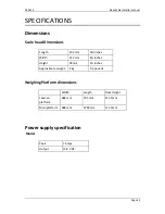
Страница 37: ...ength 232 mm 9 inches Width 212 mm 8 inches Height 90 mm 3 inches Approximate weight 2 kg 4 4 pounds Weighing Platform dimensions Width Length Deck Height Lead on platform 686 mm 795 mm 111 5mm Main p...

Страница 38: ...in metres 2 Determine the allowable resistance per metre using the following equation Resistance per metre 0 125 ohms Distance from Power Supply to Scale in metres 3 Take the following information to...

Страница 39: ...ab saddle assembly 6 Scale mounting plate assembly 4 Scale Lead on rail RHS 1 Scale Lead on rail LHS 1 Scale main rail 2 Weigh scale slab 8 Scale fastening kit 1 Scale Junction box assembly 1 Scale XD...

Страница 40: ...E OF MANUFACTURE AND SERIAL NUMBER Scale date of manufacture and serial number The label detailing the date of manufacture and the serial number is on the inside of the fold out support stand Y Y W W...

Отзывы: