GAR AC/DC 180. Instructions Manual.
17
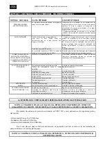
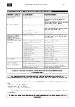
CAPITULO 5. ANOMALIAS. CAUSAS PROBABLES. SOLUCIONES POSIBLES.
SYMPTOM. ANOMALY
SYMPTOM. ANOMALY
SYMPTOM. ANOMALY
SYMPTOM. ANOMALY
PROBABLE CAUSE
PROBABLE CAUSE
PROBABLE CAUSE
PROBABLE CAUSE
POSSIBLE SOLUTION
POSSIBLE SOLUTION
POSSIBLE SOLUTION
POSSIBLE SOLUTION
GENERAL PROBLEM
NOTHING WORKS.
The machine has no voltage in one or all its vital
elements.
Make sure there is voltage at the entry to the machine;
if not the intake must be changed or the supply hose
repaired. It is advisable to see if any magnetothermal
has "blown".
The machine panels must be removed testing the
logical points of the electrical diagram.
LIMITER TRIPS
Magnetothermal switch has low gauge for the
case. There may be a shortcircuit which is what
causes the limiter to trip.
Change the magnetothermal for another larger gauge
one. It is important for the magnetothermal switch to
have a characteristic slow type curve. In the event that
the electrical installation has limited power the welding
work must be tested at lower current levels.
Coil burnt (Primary)
Change coil.
Connection is made to 220 V when the power
supply was 380 V.
Change position of on/off switch. Place the safety
switch into its correct position.
ALTHOUGH THE MACHINE IS
CONNECTED AND WITH LIGHT
K ON, THE MACHINE DOES NOT
CARRY OUT THE WELDING
OPERATION
Defect in the electrical wiring diagram.
Test internal connections. Test switch points, voltage at
transformer ouput (40V approximately)
IT WORKS AT LOW INTENSITY
The electrical supply is not correct.
Change the supply intake.
Supply cables broken or badly connected.
Repair connection.
Switch broken
Change switch.
Loose coil or connection.
Repair connection.
Coil burnt (Primary)
Change coil.
One phase is missing
Repair electrical connection
Secondary coil burnt
Change coil
Diodes deteriorated
Change rectifier
Blocks broken
Change blocks.
THERE ARE NOISES
Metal shell loose
Check and screw shell
Spirals loose in one of the coils
Change or varnish the coil
THE ELECTRODE BURNS IN THE
T.I.G. WELDING
No protection gas
Set at a suitable flow volume.
Excessive welding intensity for a certain electrode Decrease welding current or change electrode for
another one with greater diameter
Use of inverse polarity
Place the electrode at negative pole
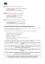
ANY WORK ON THE EQUIPMENT MUST BE CARRIED OUT BY SPECIALISED PERSONNEL
BOTH AT THE BEGINNING AND END OF A REPAIR CHECK THE EQUIPMENT INSULATION LEVELS.
DISCONNECT THE ELECTRONIC PLATES WHEN MEASURING THE INSULATION.
The insulation measuring instrument will have 500 V D.C. and will be applied at the following points of the
circuit:
- Supply-Earth: RA>50 Mohms
- Welding-Earth: Ra>50 Mohms
- Supply-Welding: Ra>50 Mohms
In the event that lack of insulation is observed it is likely that this is due to the accumulation of metal dust on
the inside of the equipment.
BOTH AT THE BEGINNING AND END OF A REPAIR, BLOW THE INSIDE OF THE EQUIPMENT WITH
BOTH AT THE BEGINNING AND END OF A REPAIR, BLOW THE INSIDE OF THE EQUIPMENT WITH
BOTH AT THE BEGINNING AND END OF A REPAIR, BLOW THE INSIDE OF THE EQUIPMENT WITH
BOTH AT THE BEGINNING AND END OF A REPAIR, BLOW THE INSIDE OF THE EQUIPMENT WITH
COMPRESSED AIR.
COMPRESSED AIR.
COMPRESSED AIR.
COMPRESSED AIR.


