SMART CUT 1000
21
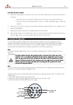
Account for the alarm indicator:
Account for the alarm indicator:
Account for the alarm indicator:
Account for the alarm indicator:
1)
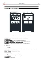
When the machine appears over-heat or over-current , the yellow indicator (lamp 2) on the front panel will on
continually.
o
Over-heat: The alarm will release after the period of fan cooling. You can restart the machine.
o
Over-current: The alarm is beyond retrieve. You must ask the qualified technician to check the
machine.
2)
When any of the torch parts (include Tip, electrode, shield cup and gas distributor) isn’t installed, the red
indicator (lamp 3) glitters.
3)
When the air pressure is too lower, the indicator (lamp 3) will on continually.
4)
When the gas distributor is un-installed only, there is not alarm while operating the machine, and when you
press the trigger, there is no arc and no load as well. Open the torch and check it.
4.4
About the CUT voltage divider
About the CUT voltage divider
About the CUT voltage divider
About the CUT voltage divider
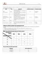
The CUT power supplies are equipped with an optional, factory-installed, four-position voltage divider that is
designed to be safely connected without tools. The built-in voltage divider provides a scaled down arc voltage of
20:1, 30:1, 40:1, and 50:1 (maximum output of 18 V). An optional receptacle on the rear of the power supply
provides access to the scaled down arc voltage and signals for arc transfer and plasma start.
Note
Note
Note
Note:
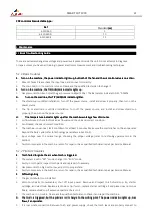
The factory presets the voltage divider to 20:1. To change the voltage divider to a different setting, refer to the
section on
the next page.
The factory
The factory
The factory
The factory----installed internal voltage divider provides a maximum of 18 V under open circuit
installed internal voltage divider provides a maximum of 18 V under open circuit
installed internal voltage divider provides a maximum of 18 V under open circuit
installed internal voltage divider provides a maximum of 18 V under open circuit
conditions. This is an impedance
conditions. This is an impedance
conditions. This is an impedance
conditions. This is an impedance----protected functional extra low voltage (ELV) output to prevent
protected functional extra low voltage (ELV) output to prevent
protected functional extra low voltage (ELV) output to prevent
protected functional extra low voltage (ELV) output to prevent
shock, energy, and fire under normal conditions at the ma
shock, energy, and fire under normal conditions at the ma
shock, energy, and fire under normal conditions at the ma
shock, energy, and fire under normal conditions at the machine interface receptacle and under
chine interface receptacle and under
chine interface receptacle and under
chine interface receptacle and under
single fault conditions with the machine interface wiring. The voltage divider is not fault tolerant
single fault conditions with the machine interface wiring. The voltage divider is not fault tolerant
single fault conditions with the machine interface wiring. The voltage divider is not fault tolerant
single fault conditions with the machine interface wiring. The voltage divider is not fault tolerant
and ELV outputs do not comply with safety extra low voltage (SELV) requirements for direct
and ELV outputs do not comply with safety extra low voltage (SELV) requirements for direct
and ELV outputs do not comply with safety extra low voltage (SELV) requirements for direct
and ELV outputs do not comply with safety extra low voltage (SELV) requirements for direct
connection to computer prod
connection to computer prod
connection to computer prod
connection to computer products.
ucts.
ucts.
ucts.
Note
Note
Note
Note:
The cover on the machine interface receptacle prevents dust and moisture from damaging the receptacle when not
in use. This cover should be replaced if damaged or lost.
Installation of the machine interface cable must be performed by a qualified service technician. To install a machine
interface cable:
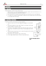
1. Turn OFF the power and disconnect the power cord.
2. Remove the machine interface receptacle’s cover from the rear of the power supply.
3. Connect the machine interface cable to the power supply.
Содержание 223001000C
Страница 26: ......
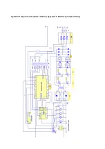
Страница 27: ...Apéndice 1 Esquema del sistema eléctrico Appendix 1 Electrical principle drawing ...
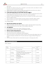
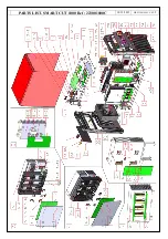
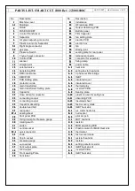
Страница 28: ...PARTS LIST SMART CUT 1000 Ref 223001000C 14 12 2015 HR 223001000C V0 1 2 ...
Страница 30: ......
Страница 31: ......


