Features and Options CommandPLUS Series Desktop Console Installation and Service Manual
09/07 44
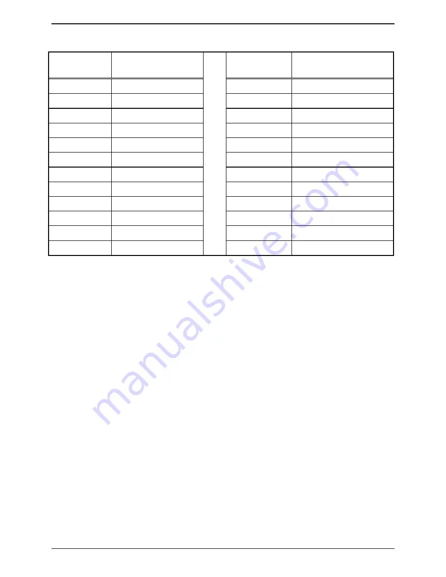
Table 16. Telco Interface Pin Connectors
Pair # (Pin #)
Pin Function (Pin #)
(for dc pos, neg)
Pair # (Pin #)
Pin Function (Pin #)
(for dc pos, neg)
1 (1, 26)
TX 1 (14, 15)
13 (13, 38)
TX 7 (8, 9)
2 (2, 27)
RX 1 (1, 2)
14 (14, 39)
RX 7 (10, 11)
3 (3, 29)
TX 2 (3, 4)
15 (15, 40)
TX 8 (12, 13)
4 (4, 29)
RX 2 (5, 6)
16 (16, 41)
RX 8 (24, 25)
5 (5, 30)
TX 3 (8, 9)
17 (17, 42)
TX 9 (14, 15)
6 (6, 31)
RX 3 (10, 11)
18 (18, 43)
RX 9 (1, 2)
7 (7, 32)
TX 4 (12, 13)
19 (19, 44)
TX 10 (3, 4)
8 (8, 33)
RX 4 (24, 25)
20 (20, 45)
RX 10 (5, 6)
9 (9, 34)
TX 5 (14, 15)
21 (21, 46)
TX 11 (8, 9)
10 (10, 35)
RX 5 (1, 2)
22 (22, 47)
RX 11 (10, 11)
11 (11, 36)
TX 6 (3, 4)
23 (23, 48)
TX 12 (12, 13)
12 (12, 37)
RX 6 (5, 6)
24 (24, 49)
RX 12 (24, 25)
Button/Elastomer Replacement (XCP0110A)
This button kit provides replacement key panel buttons for the console. The kit includes replacement keys
for a 4-channel section of the console in addition to the
MONITOR
and
TRANSMIT
keys. Each of the
rubber elastomers and a variety of other buttons are also provided with this kit.
To Remove a Button
Using needle nose pliers, grasp the top and bottom of the button as close to the base of the button as
possible without scratching the console. Squeeze in at the top and bottom points and gently pull the button
out.
To
Install
a
Button
Using needle nose pliers, squeeze in at the top and bottom of the button. Slide the button into the
appropriate place on the key panel until it snaps securely into place.


