manualshive.com logo in svg
background image

15


REV. 6/22


GB786/204 INSTALLATION TOOL


WARNING

Disconnect tool from its air source before disassembly.
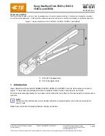
 

OVERHAUL


HEAD


AIR VALVE


HANDLE


To inspect air cylinder bore, remove handle base (870175) . Any further disassembly will require removal of the manifold

-

handle (786303).


For complete disassembly.


1.


Remove handle base (870175).


2.


Holding tool upright, remove six socket head cap screws (400062 & 400063). Lift manifold

-

handle (786303) from handle (870149) and 

set aside o'ring (404550) and head gasket (870143).


3


Empty all hydraulic oil into an approved container and dispose of in accordance with the material safety datasheet.


4


Place piston rod wrench (745155) down into top of power cylinder (786131) and into the slot of piston rod assembly (786133). While 

holding the piston rod wrench (745155), remove cotter pin (401314), then slotted nut (S302) using a 7/16" socket wrench or an 

adjustable wrench. Still holding piston rod wrench (745155), remove air piston (870169) using power cylinder tool assembly (704151).


5


When air piston (870169) is completely free from piston rod assembly (786133), insert threaded end of power cylinder tool assembly 

(704151) into bottom of air cylinder and remove air piston (870169).


6


After removal of air piston (870169), slide piston rod assembly (786133) back up to the end of its travel. Using packing plug 

wrench (756151) remove packing plug (870166).


7


With packing plug (870166) removed, power cylinder (786131) can be removed by pushing on power cylinder tool assembly (704151) 

when inserted into top of power cylinder (786131).


To reassemble the handle (870149).


1.


Reverse the above procedure, being certain that all o'rings are properly lubricated before installation. Torque packing plug (870166) 

to 45 foot lbs. (61 Nm).


2.


Attach the seal guide (870201) to the piston rod assembly (786133) and tap the piston rod assembly (786133) through the packing plug 

(870166).


3.


Attach air piston (870169) and slotted nut (S302). Torque slotted nut (S302) to 40 inch lbs. (4.52 Nm).


4.


Attach air piston (870169) to piston rod assembly (786133). Insert cotter pin (401314).


5.


With the piston rod in the down position, fill oil passage on top of handle (870149) with automatic transmission oil, Dexron® III or 

equivalent. When looking at top of handle (870149) the oil passage is the hole that has a counterbore for (404550) o'ring.


6.


Replace head gasket (870143) and o'ring (404550), just prior to replacing cylinder (204300). Torque all screws to manual specifications.


(See Filling & Bleeding procedures pgs. 11

-

12) & (See torque specs. pg. 10).


1.


Remove pin (744149) and muffler (744143).


2.


Insert valve extractor (S1178) into end of valve plug (744142) and pull it out.


3.


Using the same procedure, pull out valve spool assembly (743142).


4.


It should never be necessary to remove valve sleeve (743144) unless the ports in the valve sleeve (743144) are plugged from 


contaminated air. If ports are plugged, use needle nose pliers to grasp end of spring (744144), turning clockwise and pulling to 


dislodge from groove in casting. Valve spring installation tool (744251) will facilitate the proper installation of the spring (744144).


5.


Valve sleeve (743144) can be pulled out using valve sleeve removal tool (744152).


1.


Disconnect hydraulic hose assembly (A

-

1437) and air line (204122) from manifold

-

handle (786303) and drain hoses into a container.


2.


Push piston assembly (204203) back to rear of the cylinder (204300) to empty all oil from the tool. Push piston assembly (204203) 


back to the front of the cylinder (204300).


3.


Unscrew socket head cap screw (206118) from retaining ring (206117). Use a spanner wrench to remove retaining ring (206117).


4.


Push piston assembly (204203) back until cylinder cap assembly (206115) falls out of cylinder (204300). Push piston assembly 


(204203) out the rear of the cylinder (204300). Using a small blunt object, remove o'rings and back

-

up rings from components.


Clean parts mineral spirits or other o'ring compatible solvent being sure to clean o'ring grooves. Inspect components for scoring, 

excessive wear or damage.


Reassembly sequence is opposite of disassembly. Coat hose fitting threads with a non

-

hardening Teflon® thread compound such as 

Slic

-

tite® (GAGE BILT part no. 403237). 


Содержание GB786

Страница 1: ...WIDE E MAIL US FOR A DISTRIBUTOR NEAR YOU GB786 204 INSTALLATION TOOL ORIGINAL INSTRUCTIONS 44766 Centre Court Clinton Twp MI 48038 USA Ph 1 586 226 1500 Fax 1 586 226 1505 solutions gagebilt com www...

Страница 2: ...cations 4 Description of Functions 5 Warnings 6 Principle of Operation 7 How to set up the GB786 204 8 How to use the GB786 204 9 Maintenance 10 Filling Bleeding 11 12 Troubleshooting 13 Overhaul 14 1...

Страница 3: ...equent user in repairing or replacing defective goods or if the goods covered by this warranty are reworked or subjected to any type of additional processing This warranty is void if Seller is not not...

Страница 4: ...s 23 1 kN at 90 psi 6 2 bar air pressure at the air inlet The GB786 204 comes with 8 ft 2 4 m of hose and a remote actuator The GB204 cylinder when held in your hand weighs just 2 0 lbs 0 91 kg while...

Страница 5: ...6 204 INSTALLATION TOOL DESCRIPTION OF FUNCTIONS Image may not reflect actual tool Head Cylinder Actuator Assembly Air Air Line Hydraulic Hose Return Hydraulic Hose Pull Air Inlet Handle Manifold Hand...

Страница 6: ...ue to the tool weight it is recommended safety shoes be worn during operation 11 It is recommended tool be operated not more than 50 out of every 60 minutes where prolonged use is expected REPETITIVE...

Страница 7: ...the rear of the head cylinder is directed to the bottom of the piston rod assembly inside the handle assembly The internal components of the attached nose assembly are also moving with the piston asse...

Страница 8: ...whipping WARNING Always disconnect air supply when tool is not in use to prevent accidental start up WARNING Ensure there is adequate clearance for tool and operator hands CAUTION Do not use beyond t...

Страница 9: ...at eye protection hearing protection and safety boots be worn at all times while handling this equipment WARNING The users or the user s employer must assess specific risks that could be present as a...

Страница 10: ...or tool repair Inspect all hoses and couplings for wear damage and leaks Replace Repair if necessary See hydraulic thread preparation below Verify that hydraulic hose fittings and couplings air and el...

Страница 11: ...303 8 Attach air bleeder assembly 704153 to the pressure side marked P on the rear of cylinder 204300 9 Squeeze fill bottle 745263 on manifold handle 745303 until no air rises into air bleeder assembl...

Страница 12: ...old handle 786303 Torque to 35 40 in lbs 3 95 4 52 Nm Do not over tighten 4 With tool connected to air slowly loosen button head cap screw 402482 marked P on back of cylinder 204300 CAUTION TOOL IS UN...

Страница 13: ...ir valve and the piston assembly 204203 will retreat to its full stroke without returning b If o ring 400787 on valve plug 870158 is worn or damaged replace c If o rings 400780 on valve spool assembly...

Страница 14: ...ck up rings screws washers and gasket can achieve a complete overhaul TOOL DISPOSAL 1 When tool life is met drain hydraulic oil from tool and dispose of the hydraulic oil in accordance with the safety...

Страница 15: ...ch air piston 870169 to piston rod assembly 786133 Insert cotter pin 401314 5 With the piston rod in the down position fill oil passage on top of handle 870149 with automatic transmission oil Dexron I...

Страница 16: ...16 REV 6 22 GB786 204 INSTALLATION TOOL PARTS LIST 1 204203 Piston Assembly includes 403810 401114 2 206115 Cylinder Cap Assembly includes 405758 401105 405832...

Страница 17: ...LIST WARNING This tool incorporates a patented hydraulic relief valve When overhauling tool o ring A 287 back up ring 401101 retaining ring 400936 and spring 50806 must be replaced Failure to do so co...

Страница 18: ...is material undergoes combustion ACCIDENTAL RELEASE MEASURES Protective Measures Eliminate all sources of ignition in vicinity of spilled material Spill Management Stop the source of the release if yo...

Страница 19: ...4D 37OS 1 8 MBC04 204D 27OS MBC04 204D 37OS 5 32 MBC05 204D 27OS MBC05 204D 37OS 3 16 MBC06 204D 27OS MBC06 204D 37OS 13 64 GS8 204D 32OS GS8 204D 42OS 17 64 GS10 204D 32OS GS10 204D 42OS GP M GP LGP...

Страница 20: ...lt also supplies pin collar swage inspection gages to certify correct swage installation Sold Separately Grip Gage GB105093 For NAS LOCKBOLTS and blind fasteners Sold Separately Accessories Cont Appro...

Страница 21: ...les Sold Separately GB745 204 Stroke 500 12 7mm Hand held weight 1 5 lbs 68 kg Entire tool weight 9 lbs 4 kg Pull load 5 600 lbs 24 9 kN Standard Hyd Hose Length 8ft 2 4m 5ftHyd Hosesarerecommendedwit...

Страница 22: ...ength 12ft 3 7m Hydraulicpowerunitisrequiredtoruntool soldseparately ContactGageBiltformoreinformation Alternative Styles Sold Separately GB204ASH Stroke 500 12 7mm Hand held weight 3 5 lbs 1 58 kg En...

Страница 23: ...23 REV 6 22 GB786 204 INSTALLATION TOOL This page intentionally left blank...

Страница 24: ...I DUPONT DE NEMOURS CO LUBRIPLATE IS A REGISTERED TRADEMARK OF FISKE BROTHERS REFINING CO SLIC TITE IS A REGISTERED TRADEMARK OF LA CO INDUSTRIES INC Riveter Kits Available Sold Separately Gage Bilt...

Отзывы: