


- 3 -
3. JUMPER SETTINGS & FIELD WIRING FOR SERIAL COMMUNICATIONS
3.1 SAFETY WARNINGS
Digital panel meters, counters and timers may be powered with AC (mains) from 85-264V ac or
90-300V dc with the high voltage power supply option, or 12-30V ac or 10-48 Vdc with the low
voltage power supply option. To avoid the possibility of electrical shock or damaging short
circuits, always unplug the device before opening the case. Please refer to the respective device
manuals for full safety information and instruction on how to open the case. Signal wiring changes
external to the case can be made safely while the units are under power.
3.2
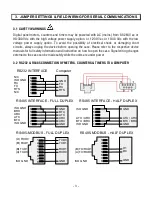
RS232 & RS485 CONNECTION OF METERS, COUNTERS & TIMERS TO A COMPUTER
6
5
4
3
2
1
N/C
ISO GND
RX
TX
RTS
N/C
GND
TX
RX
RTS
RS232 INTERFACE Computer
6
5
4
3
2
1
ISO GND
BRX
ARX
ATX
BTX
ISO GND
GND
BTX
ATX
ARX
ARX
GND
RS485 INTERFACE - FULL DUPLEX
6
5
4
3
2
1
ISO GND
ATX / ARX
BTX / BRX
ISO GND
GND
ATX / ARX
BTX / BRX
GND
RS485 INTERFACE - HALF DUPLEX
1
2
3
4
5
6
7
8
(A') RXD0
(B') RXD1
(B) TXD1
(A) TXD0
ISO GND
TXD0
TXD1
RXD1
RXD0
GND
RS485-MODBUS - FULL DUPLEX
RS485-MODBUS - HALF DUPLEX
1
2
3
4
5
6
7
8
(B) TX/RXD1
(A) TX/RXD0
ISO GND
D1
D0
GND