


- 23 -
8. APPENDIX A: DPM MEMORY ADDRESSES AND DATA DEFINITIONS
8.1 DPM 1-BYTE RAM MEMORY DATA
(L) = Lower memory, (U) = Upper memory
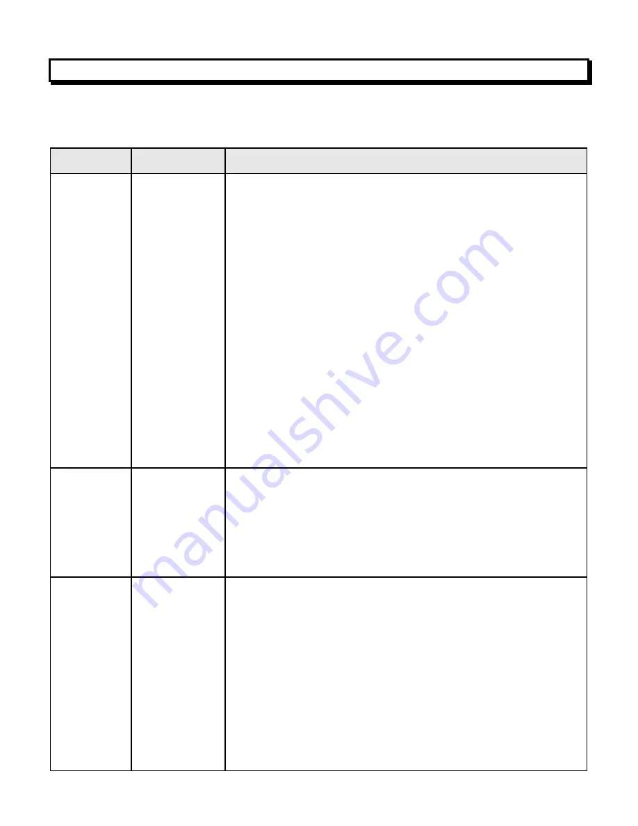
Hex Address
Item Name
Bit Assignment
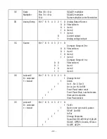
DE (L)
Configuration
Bit 7 6 5 4 3 2 1 0
0 Linear data
1 Custom curve (Extended DPM)
0
Spare
0
No Auto-Tare
1
Auto-Tare
0 0
Peak button displays Peak
0 1
Peak button displays Valley
1 0
Peak b. displays Peak then Valley
1 1
Peak button tares the meter
0 0 0
Not rate
0 0 1
Rate x 0.1
0 1 0
Rate x 1
0 1 1
Rate x 10
1 0 0
Rate x 100
1 0 1
Rate x 1000
1 1 0
Rate x 10,000
BF (L)
Analog Setup
Bit 7 6 5 4 3 2 1 0
0 Analog output unfiltered
1 Analog output filtered
0 0 0-20 mA current output
0 1 0-10V voltage output
1 0
4-20 mA current output
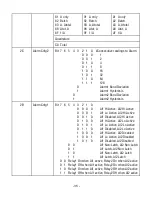
69 (L)
Serial Cnfg3
Bit 7 6 5 4 3 2 1 0
0 0 0 Send Reading
0 0 1 Send Peak
0 1 0 Send Valley
0 1 1 Send R Peak
1 0 0 Send R Peak + Valley
0
<CR> or <CR><LF> at end of all Items
1
<CR> or <CR><LF> at end of each Item
(if no Alarm character)
0
Non-latching RTS
1
Latching RTS